Circuit board maintenance is a core skill in the field of electronic technology, widely used for fault repair in industrial equipment, consumer electronics, and communication systems. Whether it is frequency converters in industrial automation equipment PLC, Mastering scientific maintenance methods for mobile phones and computer motherboards in daily life can significantly reduce maintenance costs and extend equipment lifespan. This article will explain how to repair Printed Circuit Board(PCB), including key steps, common tools, and precautions, to help readers quickly get started.
Table of Contents
1、 Preparation and fault diagnosis before maintenance
1. Information collection and preliminary judgment
-Fault phenomenon record: Detailed record of equipment fault manifestations (such as inability to turn on, abnormal signal, etc.), inquire about the operating environment and historical maintenance records of the user when the fault occurred. For example, if the frequency converter frequently reports overcurrent faults, priority should be given to checking the drive circuit or current detection module.
-Appearance inspection: Observe the circuit board for burnt marks, capacitor bulges, solder joint detachment, or foreign object contamination. For example, if the top of an electrolytic capacitor protrudes or leaks, it needs to be replaced immediately.
2. Tool preparation
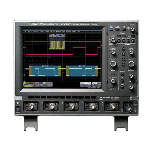
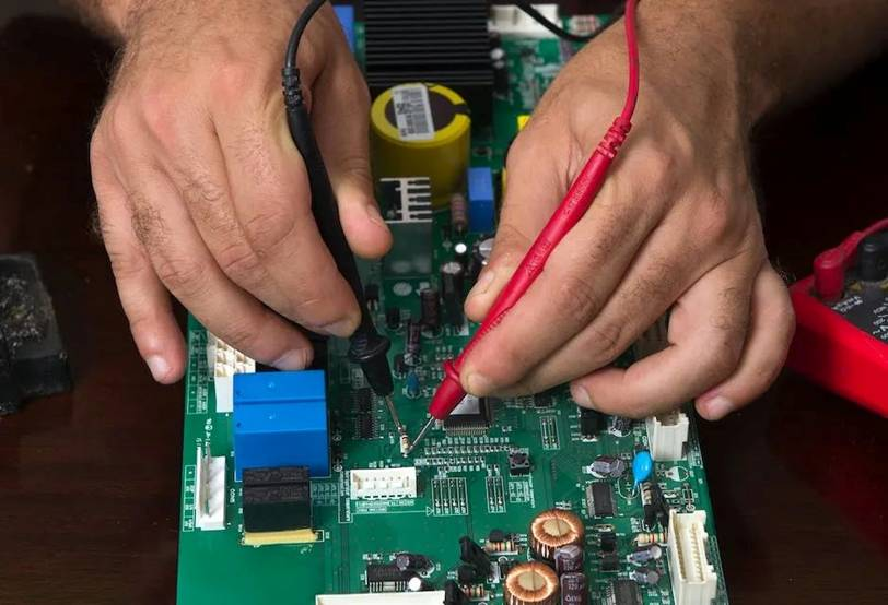
-Basic tools: multimeter (for detecting continuity and voltage), oscilloscope (for analyzing signal waveforms), hot air gun (for disassembling soldering components), soldering iron (for soldering repair).
-Advanced equipment: BGA rework station (for processing chip level soldering), logic analyzer (for debugging digital signals), infrared thermal imager (for locating overheated components).
2、 Core maintenance steps and techniques
1. Static detection: preliminary investigation when not turned on
-Resistance test: Use a multimeter to measure the resistance between the power supply and ground, which should be ≥ 70 Ω normally. If the resistance is too low, there may be short-circuit components (such as broken capacitors or diodes).
-Key node detection: Focus on checking fuses, crystal oscillators, and reset circuits. For example, when the crystal oscillator has no output, it is necessary to disconnect the peripheral chips and investigate them one by one.
2. Dynamic testing: functional verification after power on
-Power module detection: Measure whether each voltage output is stable (within ± 5% error), and use an oscilloscope to observe whether the ripple exceeds the standard. If the switch power supply is abnormal, check the PWM controller and MOS transistor.
-Signal tracking method: Inject signals (such as pulses or sine waves) from the input end and gradually detect signal attenuation or distortion points along the circuit path. For example, audio amplifier faults can be detected step by step through the input terminal to determine the gain of the amplification stage.
3. Component replacement and repair
-Substitution method: For suspected damaged chips (such as CPUs and operational amplifiers), replace them with genuine products of the same model for testing. For example, when the PLC has no output, priority should be given to replacing the control chip.
-Welding technique: Use a constant temperature soldering iron (350 ℃± 10 ℃) to avoid thermal damage, and BGA chips need to be precisely aligned and soldered with the help of a repair table.
3、 Advanced processing techniques for complex faults
1. Comparison method and reference board application
-If there are multiple circuit boards of the same model, the fault can be located by comparing the voltage and waveform differences of key nodes. For example, comparing the bus signals of two industrial control boards to identify abnormal nodes.
2. Software assisted diagnosis
-For circuit boards containing microcontrollers, use a programmer to read fault codes or reset EEPROM data. For example, when a frequency converter reports an encoder fault, it is necessary to calibrate the encoder parameters.
3. Consideration of environmental and aging factors
-Circuit boards that operate for a long time are susceptible to moisture and dust, and should be cleaned and sprayed with three proof paint to prevent moisture. For connectors with severe oxidation, they can be soaked in anhydrous alcohol and re plugged.
4、 Safe operation and precautions
1. Anti static measures
-Wear an anti-static wristband before maintenance, and lay a grounded conductive pad on the workbench to avoid electrostatic breakdown of sensitive components (such as CMOS chips).
2. Staged power on test
-When powering on for the first time, use a voltage regulator to gradually increase the voltage and observe for any abnormalities such as smoke or odor. For example, after repairing the power board, it is necessary to start testing from low voltage (such as 5V).
3. Document recording and spare parts management
-Record the maintenance process and component replacement parameters of each circuit board, establish a spare parts inventory (such as commonly used capacitor and resistor specifications), and improve subsequent maintenance efficiency.
5、 Analysis of Maintenance Cases
-Case 1: Industrial touch screen without display
Fault phenomenon: The touch screen is black but the backlight is normal.
Repair process:
1. Measure that the power supply voltage of the display screen is normal (5V).
2. Using an oscilloscope to detect the LVDS signal line, abnormal differential signal amplitude was found.
3. Troubleshooting after replacing the screen cable.
-Case 2: Inverter overcurrent alarm
Fault phenomenon: Frequent overcurrent reports (OC fault) during operation.
Repair process:
1. Check the current detection circuit and find that the resistance value of the sampling resistor is offset.
2. Replace the precision chip resistor and calibrate the parameters before restoring.
conclusion
So, now you should know How to repair Printed Circuit Board.Circuit board maintenance is a precise work that combines theory and practice, requiring mastery of circuit principles, component characteristics, and various testing techniques. Through systematic steps (from static detection to dynamic debugging), flexible use of comparison methods and software tools, combined with rigorous safety regulations, even complex faults can be efficiently resolved. With the development of electronic technology, maintenance personnel also need to continuously learn new technologies (such as AI assisted diagnosis) to cope with the challenges of higher integration of circuit boards.