The theme of this blog is drone PCB technology, with a total of approximately 1600 words covering application scenarios, core processes, design points, and industry prospects
Drone PCB: The ‘smart nerve’ of low altitude economy, how to reshape the future of aircraft?
——Unveiling the core technology and industrial prospects of PCB in the field of unmanned aerial vehicles
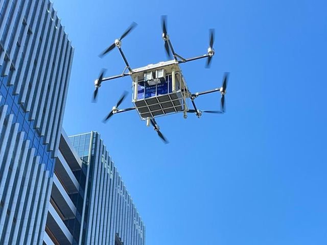
With the scale of low altitude economy breaking through the trillion level (predicted for the Chinese market in 2030), unmanned aerial vehicles are accelerating their popularity in logistics, surveying, emergency rescue and other fields. As the “nerve center” of drones, the performance of PCBs directly determines flight stability, signal accuracy, and endurance. This article will deeply analyze the application scenarios, technical processes, and design innovations of drone PCBs, providing key technical guidelines for industry partners.
Table of Contents
1、 Core application scenarios of drone PCB
1. Flight control system “brain”
-Main control module: using high-performance MCU (such as STM32F7/H7 series), it needs to support real-time processing of flight algorithms, sensor fusion, and motor control.
-Sensor integration: Gyroscope (MPU6000), barometer (BMP280), etc. are directly soldered onto the PCB, requiring a signal path of ≤ 10mm to reduce noise interference.
2. Power and Energy Management
-Motor drive circuit: capable of carrying high currents above 20A, requiring 2-3oz thick copper foil design to reduce impedance, coupled with heat dissipation vias to prevent overheating and loss of control.
–Battery management system(BMS): The intelligent charging and discharging circuit requires TVS diode protection, with voltage fluctuations controlled within ± 5%.
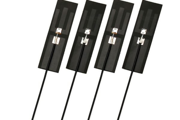
3. Communication and Navigation System
-The high-frequency module (5G/Beidou) requires accurate impedance matching to ± 5 Ω, and differential signal wiring to avoid millimeter wave signal attenuation.
2、 Four key processes: breaking the technical barriers of drone PCB
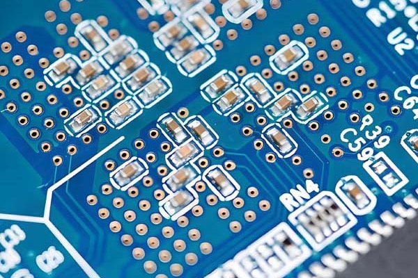
1. Lightweight and high-density integration
-Substrate innovation: FR-4 epoxy resin (standard scenario) and aluminum substrate (high heat dissipation demand) account for over 80%, while carbon fiber substrate (reducing weight by 60%) has become an emerging trend.
-Miniaturization process: The number of HDI board layers reaches 12-20, the laser micro hole aperture is ≤ 50 μ m, and the component layout density is increased by 40%.
Table: Performance comparison of mainstream substrates for drone PCB
| Substrate type | Thermal conductivity (W/m · K) | Dielectric constant (Dk) | Applicable scenarios |
| FR-4 standard board | 0.3-0.4 | 4.2-4.8 | Conventional flight control board |
| Aluminum substrate | 1.0-2.0 | 3.0-3.5 | Motor drive module |
| PTFE high-frequency plate | 0.2-0.3 | 2.0-2.5 | Millimeter wave radar |
2. High frequency and high-speed signal guarantee
-Low loss design: using modified epoxy resin (Df ≤ 0.008) or PTFE (Df ≤ 0.002) to reduce 5G signal transmission attenuation.
-3D stacking technology: Vertical copper pillar interconnection reduces wire length by 30% and reduces crosstalk rate by 15dB.
3. Reliability in extreme environments
-Seismic design: Copper block embedded support points disperse stress, and solder joints have a vibration resistance level of 10G.
-Temperature control scheme: Under the working condition of -40 ℃~85 ℃, the copper block heat dissipation array reduces the temperature of the module by 18 ℃ (measured case).
4. Anti interference shielding
-Ground plane segmentation technology isolates high-frequency noise from motors, and sensitive signal lines are treated with ground wrapping and magnetic bead filtering.
3、 Design Practical Guide: Avoiding the ‘Deadly Trap’ of Drone PCB
1. Hierarchical strategy
–4-layer golden structure: top layer (signal) → ground layer → power layer → bottom layer (signal), to eliminate power noise coupling.
-Key criteria: The distance between IMU sensor and motor drive module should be ≥ 15mm, and the length difference of SPI clock line should be<150mil.
2. Signal integrity design
-Switching to dual 45 ° wiring at a 90 ° angle, with a differential length error of ≤ 0.1mm.
-Maintain a complete ground plane below the high-speed signal line, with impedance continuity fluctuations of less than 5%.
3. Thermal management optimization
-A heat dissipation via array (diameter 0.3mm/spacing 1mm) is arranged around the power device, reducing thermal resistance by 40%.
4、 Industrial prospects driven by low altitude economy
1. Market explosion
By 2025, the penetration rate of logistics drones will exceed 80%, and the growth rate of the agricultural drone market will reach 30%, driving a surge in PCB demand.
2. Technology integration
-AI+PCB design: Intelligent cabling tool automatically optimizes EMC performance, resulting in a 25% increase in yield.
-Green manufacturing: The proportion of lead-free tin spraying process has exceeded 60%, and water-based solder mask ink reduces VOC emissions.
3. Customization trend
eVTOL aircraft drives the demand for rigid flex joint plates, and the bending life of flexible circuits reaches 100000 times.
Conclusion
Using precise “circuit genes” to support the dream of flying
The evolution history of drone PCB from 0.2mm ultra-thin board to 20 layer HDI stack is also a revolutionary history of low altitude economy. As the lifeline of low altitude aircraft, only by deeply integrating materials science, signal engineering, and environmental adaptability can we create a smart heart that conquers the clouds. Your company is deeply involved in the PCB manufacturing field, focusing on three major directions: high-frequency materials, copper block heat dissipation, and micro hole technology, to seize the trillion level low altitude economic opportunities.
We are a professional Chinese drone PCB manufacturer that provides high-quality drone PCB manufacturing services. We have advanced production equipment and an experienced team, committed to providing customers with drone PCB solutions that meet various needs.