Table of Contents
Executive Summary
The Thermal Expansion Coefficient (CTE) is a critical parameter in printed circuit board (PCB) design and manufacturing that significantly impacts product reliability, performance, and longevity. As electronic devices continue to evolve toward higher densities, increased power requirements, and more demanding operating environments, understanding and managing CTE has become increasingly crucial for preventing mechanical failures, interconnect fractures, and signal integrity issues. This comprehensive guide explores CTE fundamentals, material selection strategies, design considerations, and testing methodologies to help electronics manufacturers optimize their PCB designs for enhanced thermal performance and reliability across various applications.
1. Understanding Thermal Expansion Coefficient (CTE) in PCB Context
1.1 CTE Fundamentals and Definition
The Coefficient of Thermal Expansion (CTE) is defined as the rate at which a material expands or contracts per unit temperature change, typically measured in parts per million per degree Celsius (ppm/°C) . In practical terms, CTE quantifies how much a PCB material will change in dimensions when subjected to thermal variations during manufacturing, assembly, and operational life cycles. This parameter becomes particularly critical in modern electronics where components with different CTEs are interconnected, creating potential points of failure during temperature fluctuations.
All materials naturally expand when heated and contract when cooled, but the key challenge in PCB design arises from the mismatch between CTE values of different materials within the assembly . When materials with different expansion rates are bonded together, temperature changes induce mechanical stress that can lead to cracking, delamination, or connection failures. This fundamental physical phenomenon makes CTE management a cornerstone of reliable PCB design, especially for applications exposed to significant temperature variations or thermal cycling.
1.2 CTE Directionality in PCB Materials
PCBs exhibit different CTE characteristics along different axes due to their composite nature and anisotropic material properties:
•X-Y Axis CTE: In the plane of the board, the presence of glass fiber reinforcement significantly constrains thermal expansion, typically resulting in CTE values of 12-18 ppm/°C for standard FR-4 materials . This relatively low in-plane expansion is crucial for maintaining alignment between components and pads during temperature variations.
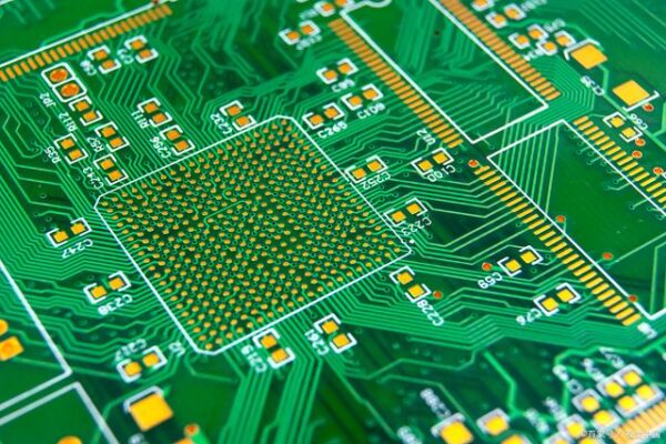
•Z-Axis CTE: Through the thickness of the board, the absence of constraining reinforcement allows for much greater expansion, typically 55-60 ppm/°C for standard FR-4 materials below the glass transition temperature (Tg) . This substantial difference between X-Y and Z-axis CTE presents particular challenges for plated through-holes and vias, which must accommodate the differential expansion between the copper plating and the substrate material.
The anisotropic nature of PCB CTE necessitates different design strategies for addressing in-plane versus through-thickness expansion effects, making understanding this directionality essential for developing reliable multilayer boards and high-density interconnects.

2. CTE-Related Failure Mechanisms in PCBs
2.1 Plated Through-Hole (PTH) Failures
The Z-axis CTE mismatch between copper plating (approximately 16-18 ppm/°C) and the PCB substrate (55-60 ppm/°C for FR-4) creates one of the most common CTE-related failure mechanisms in printed circuit boards . During thermal cycling, the differential expansion rates generate repeated mechanical stress on the plated through-hole barrels, potentially leading to:
•Barrel Cracking: Cyclic stress can initiate and propagate cracks in the copper plating of PTHs, eventually resulting in open circuits or intermittent connections .
•Pad Lifting: Excessive Z-axis expansion can separate copper pads from the substrate material, particularly after multiple thermal cycles during assembly or operation.
•Interconnect Fractures: The stress concentration at the interface between PTH barrels and inner layer connections can cause fatigue failures, especially in boards with high layer counts or thick constructions.
These failure mechanisms become increasingly problematic with the higher processing temperatures of lead-free assembly, where thermal excursions can reach 260°C during reflow soldering, significantly stressing the PTH structures.

2.2 Solder Joint Reliability
CTE mismatch between components and the PCB substrate represents another critical failure mechanism in surface mount assemblies . When components such as ceramic chip carriers (CTE ≈ 6 ppm/°C) are mounted on standard FR-4 substrates (CTE ≈ 15-18 ppm/°C in X-Y direction), the differential expansion during temperature cycling induces shear stress on solder joints:
•Thermal Fatigue: Repeated thermal cycling causes work hardening and eventual crack propagation through solder joints, leading to increased electrical resistance and eventual failure .
•Stress Concentration: Large components such as BGAs and QFPs experience greater absolute displacement at corner joints, making these locations particularly susceptible to CTE mismatch failures.
•Rework Difficulties: CTE-related solder joint damage often becomes more pronounced during rework operations, where localized heating creates steep thermal gradients.
The trend toward larger components and finer pitch interconnections exacerbates these challenges, making CTE management increasingly critical for assembly yield and long-term reliability.
2.3 Delamination and Material Integrity
When PCB materials are exposed to temperatures beyond their designed operational range, differential CTE can cause delamination between layers:
•Z-Axis Expansion Stress: The high Z-axis CTE creates tensile stress at layer interfaces, which can exceed the bond strength when combined with thermal degradation of the resin system.
•Moisture Effects: Absorbed moisture vaporizes rapidly at high temperatures, generating additional pressure that exacerbates delamination tendencies.
•Material Degradation: Repeated over-temperature exposure can cause permanent changes to the substrate material, increasing its CTE and reducing its mechanical strength.
These failure mechanisms underscore the importance of selecting materials with appropriate CTE characteristics for the expected operating environment and thermal cycling conditions.
3. Material Selection Strategies for CTE Management
3.1 Glass Transition Temperature (Tg) and CTE Relationship
The glass transition temperature (Tg) represents a critical threshold in polymer-based PCB materials where the resin system transitions from a rigid, glassy state to a softer, rubbery state . This transition has profound implications for CTE behavior:
•Below Tg: PCB materials exhibit a relatively low, stable CTE (α1) typically around 12-18 ppm/°C in the X-Y direction and 55-60 ppm/°C in the Z-direction for standard FR-4 .
•Above Tg: The CTE typically increases significantly (α2), often by a factor of 3-4 in the Z-direction, potentially reaching 200-300 ppm/°C .
This dramatic change in CTE above Tg makes the selection of materials with appropriate Tg values critical for applications that experience elevated temperatures during operation or assembly. Higher Tg materials (generally >170°C) maintain their dimensional stability at higher temperatures, reducing the CTE-related stresses during assembly processes and in high-temperature operating environments .
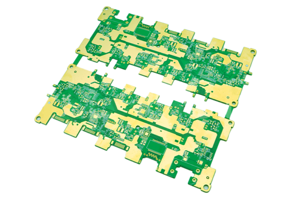
3.2 PCB Material Classes and CTE Performance
Different PCB material systems offer varying CTE characteristics, allowing designers to select appropriate materials based on application requirements:
Table: CTE Characteristics of Common PCB Materials
| Material Type | X-Y CTE (ppm/°C) | Z-CTE (ppm/°C) | Tg Range (°C) | Typical Applications |
| Standard FR-4 | 14-18 | 55-60 | 130-140 | Consumer electronics, general purpose |
| Mid-Tg FR-4 | 13-16 | 50-55 | 150-160 | Industrial controls, automotive |
| High-Tg FR-4 | 12-15 | 45-50 | 170-180 | Lead-free assembly, high-reliability |
| Rogers4350 | 12-15 | 40-50 | >280 | RF/Microwave, high-frequency |
| Polyimide | 12-15 | 45-55 | 250-260 | Aerospace, military, extreme environment |
| Metal Core | 12-20* | N/A | N/A | LED lighting, power electronics |
*X-Y CTE for metal core boards varies significantly based on metal thickness and composition
The selection of higher-performance materials often involves trade-offs between CTE performance, cost, processability, and other electrical properties, requiring careful consideration of the specific application requirements and operating conditions .
3.3 Specialized Low-CTE Materials
For applications requiring exceptional dimensional stability, several specialized material approaches are available:
•Ceramic-Filled Composites: Materials with ceramic fillers in the resin system can achieve Z-axis CTE values as low as 30-40 ppm/°C, significantly reducing PTH stress .
•Dimensionally Stable Reinforcements: Alternative reinforcement materials such as aramid fibers or specialized glass weaves can provide improved CTE matching to components.
•Metal Core PCBs: Insulated metal substrates (IMS) using aluminum or copper cores offer excellent thermal conductivity while maintaining moderate in-plane CTE, making them particularly suitable for power electronics and LED applications where thermal management is crucial .
These specialized materials typically command a cost premium but provide necessary performance for demanding applications such as aerospace, automotive, or high-reliability industrial systems.
4. PCB Design Strategies for CTE Management
4.1 Layout Considerations for CTE Compensation
Strategic PCB layout can help mitigate the effects of CTE mismatch in electronic assemblies:
•Component Orientation: Rotating components to align their CTE directionality with the board’s lower CTE direction (typically along the glass fiber weave) can minimize relative displacement.
•Symmetric Stack-up Design: Balanced material distribution across the board’s centerline helps prevent warping and twisting during thermal excursions by creating symmetric CTE behavior above and below the neutral axis.
•Copper Distribution: Balanced copper distribution across layers helps maintain uniform thermal mass and minimizes localized CTE-induced stress concentrations.
•Keep-Out Zones: Implementing appropriate keep-out zones around large components susceptible to CTE mismatch reduces stress transfer to adjacent sensitive components.
These layout strategies become increasingly important with larger board sizes, where the absolute dimensional changes due to CTE are more significant.
4.2 Via Design and Protection
Plated through-holes and vias represent critical stress concentration points in multilayer boards, requiring special design attention:
•Annular Ring Sizing: Increasing annular ring sizes provides additional margin for registration shifts caused by CTE mismatch during thermal cycling.
•Via-in-Pad Design: When using via-in-pad structures, complete filling with conductive or non-conductive material helps resist CTE-induced stress concentration.
•Teardrop Transitions: Incorporating teardrop-shaped transitions between traces and pads distributes mechanical stress more evenly, reducing the likelihood of cracking at these interfaces.
•Staggered Via Patterns: In high-density interconnect designs, staggering vias between layers reduces the cumulative effect of Z-axis expansion on reliability.
These design techniques help maintain electrical integrity despite the differential expansion between copper interconnects and the substrate material.
4.3 Thermal Management Integration
Proactive thermal management helps minimize the temperature excursions that drive CTE-related issues:
•Thermal Via Arrays: Strategically placing thermal vias under high-power components reduces the temperature delta across the assembly, minimizing CTE-driven stresses.
•Copper Thickness Optimization: Increasing copper weights in power planes improves both current carrying capacity and thermal spreading, reducing hot spots and localized thermal expansion.
•Heatsink Integration: Proper mechanical attachment of heatsinks with consideration for CTE mismatch prevents additional stress on components and the PCB.
These thermal management approaches work synergistically with CTE-specific design strategies to enhance overall reliability.
5. Testing and Characterization Methods
5.1 CTE Measurement Techniques
Several standardized methods exist for characterizing CTE in PCB materials:
•Thermomechanical Analysis (TMA): The most common technique for measuring CTE, TMA precisely tracks dimensional changes in a material sample as temperature is varied, generating data on both α1 (below Tg) and α2 (above Tg) CTE values .
•Moisture Expansion Analysis: Specialized TMA methods can characterize hygroscopic expansion, which can interact with thermal expansion in humid environments.
•Interferometric Methods: Laser-based interferometry provides extremely precise CTE measurements for critical applications requiring high accuracy.
These characterization methods provide essential data for material selection and reliability modeling, particularly for new material systems or custom formulations.
5.2 Reliability Testing Protocols
Multiple industry-standard test protocols evaluate PCB performance under CTE-driven stress conditions:
•Thermal Cycling: Subjecting assemblies to repeated temperature extremes reveals CTE-related failure mechanisms such as solder joint fatigue and interconnect fractures .
•T260, T288, T300 Testing: These tests measure the time to delamination at specified temperatures (260°C, 288°C, and 300°C), providing insight into a material’s resistance to Z-axis CTE-driven failures .
•Interconnect Stress Test (IST): This specialized methodology accelerates via barrel cracking through rapid thermal cycling, providing quantitative lifetime predictions for PTH structures.
•Highly Accelerated Life Testing (HALT): Applying combined thermal and vibration stresses identifies system-level weaknesses potentially exacerbated by CTE effects.
These test methods help validate both material selection and design approaches before committing to volume production, reducing the risk of field failures.
6. Advanced Applications and Future Trends
6.1 High-Density Interconnect (HDI) Considerations
As PCB technology advances toward finer features and higher densities, CTE management faces new challenges:
•Microvia Reliability: The smaller geometry of microvias reduces absolute displacement from CTE mismatch but increases sensitivity to material property variations.
•Sequential Lamination: Complex HDI structures with multiple lamination cycles require careful material selection to manage cumulative CTE stress.
•Embedded Components: Integrating passive and active components within the PCB stack-up introduces additional CTE interfaces that must be carefully managed.
These considerations make CTE an increasingly critical parameter in advanced packaging and integration approaches.
6.2 High-Frequency and High-Speed Design
In high-frequency applications, CTE impacts both mechanical and electrical performance:
•Phase Stability: Dimensional changes from CTE can alter transmission line lengths and characteristics, affecting phase relationships in critical RF circuits.
•Material Consistency: High-frequency laminates often have different CTE characteristics than standard FR-4, requiring special attention at material interfaces in mixed-dielectric designs.
•Connector Interfaces: CTE mismatch at connector interfaces can degrade high-frequency performance through mechanical deformation affecting impedance matching.
These factors make CTE consideration essential in communications infrastructure, aerospace systems, and high-performance computing applications.
7. Conclusion
Effective management of the Thermal Expansion Coefficient (CTE) remains a fundamental requirement for reliable PCB design across all segments of the electronics industry. As technological trends continue toward higher densities, increased power levels, and more demanding operating environments, the importance of comprehensive CTE understanding and mitigation only grows.
Successful CTE management requires a holistic approach encompassing material selection based on application requirements, design strategies that anticipate thermal mechanical stress, and validation methodologies that confirm reliability under expected operating conditions. By addressing CTE considerations early in the design process and applying the principles outlined in this guide, electronics manufacturers can significantly enhance product quality, reliability, and customer satisfaction.
The continuing evolution of PCB materials and manufacturing technologies will undoubtedly provide new tools for CTE management, but the fundamental principles of understanding thermal expansion behavior and its system-level consequences will remain essential knowledge for creating robust, reliable electronic products.
Partner with Us for Your PCB Manufacturing Needs
Successfully managing CTE challenges requires expertise in material science, design optimization, and manufacturing processes. Our specialized capabilities in advanced PCB fabrication and thermal management solutions ensure that your designs achieve optimal performance and reliability across your required temperature ranges.
Contact us today to discuss how we can support your next PCB project with technical expertise tailored to your specific application requirements and operational environment.