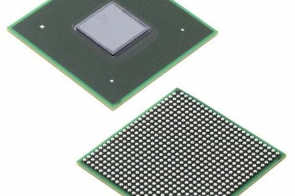
In circuit design, resistance is one of the most familiar components, and plays the role of voltage division and current limiting in the circuit.
What roles can a zero-ohm resistor play in a circuit?
1. Debugging and compatibility
We need to consider as many compatibility issues as possible when designing the PCB board, because a circuit board is fixed after physical printing and copper plating. If the compatibility issue is not fully considered in the design, it will cause a lot of inconvenience to the engineers during the board debugging stage.
For example: a certain pin of the chip has two functions, it can drive the buzzer, and it can also be used to drive LED lights. However, these two functions cannot work at the same time. At this time, a zero ohm resistor can be added to the line connecting the buzzer and the LED. The zero ohm circuit on which path is welded determines whether the buzzer or the LED lamp is driven.
2. Easy wiring
During the PCB layout and wiring phase, sometimes the wiring will always can’t get through, especially when the circuit board area is small, more wiring, less layers. If you encounter a line that takes a large circle to connect, you can consider whether you can easily skip the wire in front of you by connecting a zero ohm resistor instead of a large circle.
3. Reserved resistance position
If in the circuit design stage, a position is not sure resistance value, at this time, you can leave a welding position of the resistance and weld a zero ohm resistor. In actual circuit debugging, you can easily change the resistance of different resistance value, and then connect the appropriate resistance after debugging the determined resistance parameters.
4. Convenience test current
After designing the circuit system, it is usually necessary to test the power consumption of the entire circuit during operation. The conventional method is to calculate the power consumption by testing the current and then using the current, and the method of testing the current is usually to string the ammeter into the circuit and measure it. At this time, if a zero ohm resistor is placed where the current needs to be measured, when the measurement is required, then removed the resistor and connect the ammeter. In normal operation, just solder the zero ohm resistor.
5. Noise suppression
Due to the characteristics of the zero ohm resistor, the loop current can be effectively suppressed, thereby suppressing the noise. In fact, zero ohm resistance is not really without impedance, only superconductors can really achieve zero impedance. Therefore, the zero ohm resistor actually plays a role of attenuation.
6. Security protection
You can often see many pinheads on many circuit boards, which need to be terminated with jumper caps. Or use the DIP switch to control whether the circuit is closed. Although these two methods will be more convenient in the debugging stage, it is best to use them as little as possible when making the product. In a high-frequency circuit, the vacant pinhead equivalent to an antenna, so it is easy to interfere with the signal. In addition, the DIP switch is easily messed up by uninformed persons, causing errors in the circuit system. Therefore, for safety reasons, it is best to use zero ohm resistors instead of pinheads and DIP switches. Not only can avoid misuse, but also reduce maintenance costs.
7. Act as a capacitor or inductance
In the high-frequency circuit system, when the zero-ohm resistance matches the characteristics of the external circuit, it can act as a small capacitor or inductance, which can solve the EMC problem well. For example, between ground and ground, or between power and chip pins.
8. Ground isolation
In chip design, the ground of analog circuits is called AVSS, and the ground of digital circuits is called VSS. AVSS and VSS are usually separated inside the chip, because the separation of the ground wire can avoid the interference between the current signals of the analog circuit and the digital circuit during operation. However, the ground wires on the board are usually connected together finally. At this time, let the chip AVSS and VSS pass the zero ohm resistance and then connect together to play a certain isolation role.