Table of Contents
Background Overview
This is the temperature range of the capacitive component:
| specifications | characteristic | temperature range | Static capacitance change rate |
| JIS | JB(B) | -25~+85℃ | ±10% |
| JF(F) | -25~+85℃ | +30~-80% | |
| EIA | X5R | -55~+85℃ | ±15% |
| X6S | -55~+105℃ | ±22% | |
| X7R | -55~+125℃ | ±15% | |
| X7S | -55~+125℃ | ±22% | |
| X8R | -55~+150℃ | ±15% | |
| Y5V | -30~+85℃ | +22~-82% |
Recommended devices with a maximum operating junction temperature of 85 ℃:

Recommended devices with a maximum operating junction temperature of 105 ℃:


Recommended devices with a maximum operating junction temperature of 125 ℃:


Recommended devices with a maximum operating junction temperature of 150 ℃:


These are the four component environmental temperature levels specified in the AEC-Q100-REV-H version specification. The step between levels 3-2-1 is 20 ℃, and the step between levels 1-0 is 25 ℃. So, it is rare to see devices with a maximum operating temperature of 95 ℃.

History and Industry Standard Practices
In the early stages of electronic component development, the industry began to establish standards to regulate the performance parameters of components, including the operating temperature range. These standards have gradually been fixed in long-term practice, forming temperature levels with intervals of 10 ℃ or 20 ℃. For example, organizations such as the Electronic Industries Association (EIA) in the United States have taken into account factors such as testing techniques, material properties, and application requirements when developing relevant standards, resulting in these temperature levels being widely accepted.
Material properties and physical and chemical limitations
The influence of temperature on material properties: Electronic components are composed of various materials, such as semiconductor materials, metal electrodes, packaging materials, etc. When the temperature rises, the physical and chemical properties of these materials will change. For example, the carrier mobility of semiconductors changes with increasing temperature. Generally, for every 10-20 ℃ increase in temperature, there will be significant changes in performance parameters such as carrier mobility. At temperatures around 85 ℃, 95 ℃, 105 ℃, and 125 ℃, changes in material properties may cause significant changes in the working state of components, such as changes in resistance values and increased dielectric losses of capacitors.
Thermal stability of materials: Different materials have different thermal stability limits. Taking capacitors as an example, the electrolyte of electrolytic capacitors will accelerate evaporation at high temperatures. When the temperature reaches a certain level, the electrolyte will dry up and cause the capacitor to fail. For some ceramic capacitors, the internal ceramic dielectric may also undergo structural changes at high temperatures. The stability differences of these materials at temperatures such as 85 ℃, 95 ℃, 105 ℃, and 125 ℃ are important factors in determining the operating temperature range. For example, the upper limit of the operating temperature for general quality electrolytic capacitors may be 85 ℃, while some high-performance ceramic capacitors can operate at 125 ℃.
Reliability and lifespan test results
Accelerated aging testing: During the development process of electronic components, a large number of reliability and lifespan tests will be conducted. Among them, high-temperature accelerated aging testing is a commonly used method. By conducting long-term tests on components in different high-temperature environments, observe their performance degradation and failure. Research has found that for every 10-20 ℃ increase in temperature, the aging rate of components accelerates and their lifespan significantly shortens.
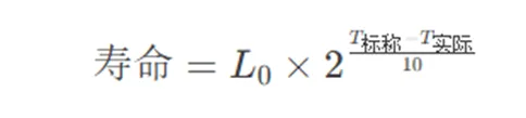
For example, components that can work normally for 10 years at 85 ℃ may only work for 2-3 years at 105 ℃. These test results provide a basis for determining the appropriate operating temperature range. The temperature levels of 85 ℃, 95 ℃, 105 ℃, and 125 ℃ were determined after considering the reliability and expected lifespan of the components at different temperatures.
Application scenarios and considerations for heat dissipation design
Different application environment temperatures: Electronic devices have various application scenarios, ranging from ordinary indoor environments to industrial high-temperature environments. For example, in ordinary consumer electronics products such as smartphones and tablets, the normal operating environment temperature generally does not exceed 40-50 ℃. However, considering the local heating and poor heat dissipation inside the device, components need to have a certain temperature margin, and a working temperature level of 85 ℃ can meet this requirement. In industrial control equipment, automotive electronics and other application scenarios, the ambient temperature may be higher. For example, electronic components in the engine compartment of a car may be exposed to high temperatures above 100 ℃, so components that can withstand 105 ℃ or 125 ℃ are needed.
Heat dissipation design and cost balance: Determining these operating temperature levels also helps with heat dissipation design. If the working temperature level of the components is low, such as only 60 ℃, stricter requirements are needed in the heat dissipation design, which may require larger heat sinks, more efficient fans, etc., which will increase the cost and volume of the equipment. Choosing the appropriate working temperature level, such as 85 ℃ or 95 ℃, can ensure the normal operation of components through reasonable heat dissipation design, such as natural convection heat dissipation or small heat dissipation devices, while meeting reliability requirements, thus achieving a balance between performance, reliability, and cost.
Finally, the step for the maximum operating junction temperature from 125 ℃ to 150 ℃ is not 10 ℃ or 20 ℃, which is a special case.