At a high temperature of nearly 50 ℃ in Cairo, Egypt, the inverter of a photovoltaic power station is operating stably with a conversion efficiency of 99.04%; And for an electric vehicle equipped with an 800V high-voltage platform, the switching loss of its main drive inverter is reduced by 60% compared to traditional solutions – behind these breakthrough performances, inverter PCB, as the physical carrier of energy conversion, is undergoing a silent revolution.
Table of Contents
1、 Inverter: the ‘translator’ of energy transformation
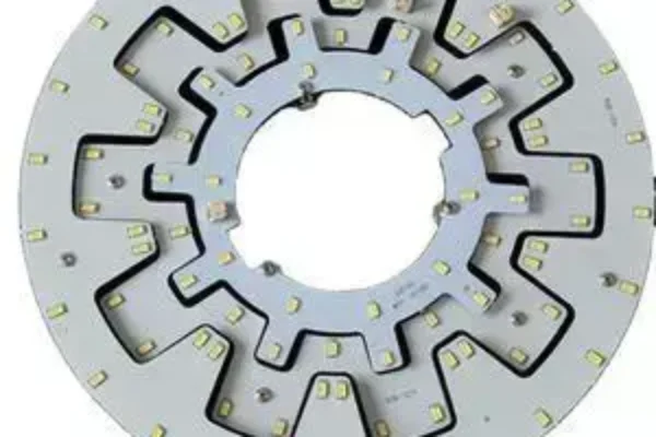
The core mission of inverters is to efficiently convert direct current (DC) to alternating current (AC), and their application scenarios are rapidly expanding
-In the field of photovoltaic power generation, the world’s leading SMA inverter achieves 76A high current transmission through PCB wiring terminals, converting solar panel DC power into grid compatible AC power. The fully automatic backup function ensures the safety of household power supply;
–Electric vehicle electric drive system: Schaeffler high-voltage embedded power module adapted to 800V platform, PCB embedded with silicon carbide chip enables inverter efficiency to exceed 99%;
-Industrial and commercial energy storage: SiC MOSFET power modules maintain a 100% pass through success rate in fluctuating power grid environments, and the thermal shock resistance of PCB substrates is increased by 100 times.
The estimated size of China’s PCB market in 2024 is 346.9 billion yuan, with new energy applications accounting for over 35%, making it the fastest-growing sub sector.
2、 The Triple Core Mission of PCB in Inverter
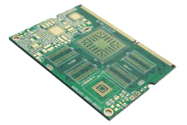
1. Physical basis of power carrying capacity
-High current channel design: The 10oz thick copper foil can carry a hundred ampere level current, with copper thickness uniformity of ± 5 μ m, reducing conduction loss;
-Heat dissipation innovation: 3mm aluminum substrate embedded in PCB reduces the junction temperature of photovoltaic inverter by 12 ℃ and achieves a conversion efficiency of 98.7%.
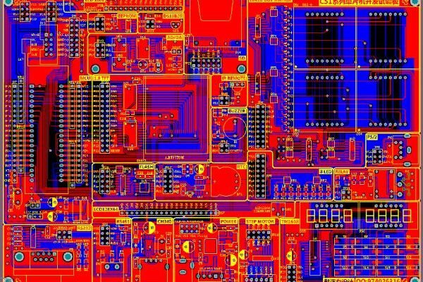
2. Precise pathway for high-frequency signals
-Impedance control technology: achieve 50 Ω± 5% characteristic impedance through SI9000 simulation, reducing 28GHz high-frequency signal reflection;
-Low loss substrate: Rogers RO4350B board has a dielectric loss (Df) as low as 0.0037, and the RF loss of 5G base stations is only 1/5 of FR-4.
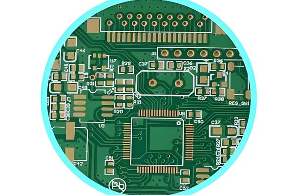
3. Space optimization for system integration
| Technical solution | Space reduction effect | Performance improvement |
| HDI micropores | 40% | 70% increase in linear density |
| Buried resistance and capacitance | 30% | signal delay reduced by 25% |
| Embedded chip packaging | 50% | Thermal resistance reduced by 35% |
Data source: Analysis of HDI board technology advantages
3、 Design Challenge and Breakthrough Path
1. Thermal Management: The Ultimate Battlefield of Energy Loss

-Three dimensional heat dissipation architecture: embedding a copper pillar array (Thermal Via Array) in an aluminum substrate, increasing the thermal conductivity to 270W/mK; The vacuum bonding process ensures that the interlayer thickness deviation is less than 0.01mm, eliminating local overheating caused by bubbles.
-Thermal simulation driven design: ANSYS Icepak simulates temperature distribution, optimizes power device layout, and controls temperature difference within 5 ℃.
2. High voltage insulation: hardcore defense against breakdown risk
Schweizer’s P ² packaging technology achieves through innovation:
-The interlayer adopts polyimide film with a compressive strength of 150kV/mm;
-The laser cutting groove isolates the high-voltage area, and the creepage distance is accurate to 0.25mm/kV.
3. Electromagnetic compatibility: the nemesis of stealth interference
-Copper surface segmentation technology: The power layer adopts a “Japanese” segmentation to reduce di/dt noise coupling;
-Magnetic bead array: 0603 encapsulated magnetic beads are deployed at the boundary of the RF region to absorb interference in the 100MHz-6GHz frequency band.
4、 Future Battlefield: Four Major Technological Fission Directions
1. Deep integration of SiC/GaN and PCB
650V SiC MOSFET fully replaces IGBT, reducing the volume of 125kW inverter module by 40% and reducing high-temperature losses by 12%.
2. Embedded power chip packaging
Directly embedding the chip between PCB layers reduces stray inductance by 60% and the switching frequency exceeds 100kHz.
3. Additive Manufacturing Revolution
Laser induced metal deposition (LIFT) achieves a linewidth of 5 μ m and supports direct writing of 0.1THz millimeter wave circuits.
4. Intelligent self diagnostic PCB
Integrated temperature/current sensor network, real-time prediction of solder joint fatigue life, fault warning accuracy>95%.
5、 Our technological barrier: redefining high reliability inverter PCB
1. Materials Innovation Laboratory
-Develop nano modified epoxy resin, Z-axis CTE matching silicon carbide chip (2.5ppm/℃), to solve the problem of solder joint cracking;
-Customize RO4835 in collaboration with Rogers ™ Mixed pressure plate reduces costs by 30% and maintains a loss tangent value of 0.0037.
2. Extreme process control capability
Comparison of Precision Manufacturing Parameters
| Parameters | Industry Standards | Our Company Standards |
| Laser blind hole accuracy | ± 15 μ m | ± 10 μ m |
| Copper thickness uniformity | ± 10% | ± 3% |
| Impedance control deviation | ± 10% | ± 5% |
| High frequency insertion loss (@ 10GHz) | 0.8dB/cm | 0.35dB/cm |
3. Full scenario testing and verification platform
–40 ℃~150 ℃ 3000 temperature cycles test (IEC 60068-2-14)
-50g acceleration mechanical impact test (MIL-STD-883)
-10kV/100A surge current withstand test
When a 0.8mm thick PCB carries 1200V high voltage, microampere current, and millimeter wave signals in harmony, it is not only the pinnacle art of electronic engineering, but also the micro cornerstone of the energy revolution. By 2027, the global high-frequency PCB market will exceed $98 billion, with inverters accounting for 40% of the market share.
Choosing to collaborate with us means that you not only receive circuit boards, but also an energy conversion hub that can withstand the impact of Sahara heat waves, Siberian cold waves, and power grid surges. Here, the direction of each micrometer of copper foil is optimized through electromagnetic field simulation, and each solder joint is verified through thousands of cold and hot cycles. When your inverter lights up thousands of lights with 99% efficiency, it is the moment of precision manufacturing and cutting-edge technology dancing together.