The global rollout of 5G is transforming industries—from smart cities to autonomous factories—with its promise of ultra-low latency (<2ms), multi-Gbps speeds, and massive device connectivity. At the heart of this transformation lie advanced printed circuit boards (PCBs), engineered to overcome unprecedented technical challenges. As 5G基站 deployments surge toward 3.67 million by 2025 , PCB innovation becomes the critical enabler for reliable, high-performance infrastructure.
Table of Contents
5G’s Technical Demands: Why Conventional PCBs Fall Short
1. Millimeter-Wave Signal Integrity
5G’s shift to high-frequency bands (28/39/77 GHz) amplifies signal attenuation and skin effect losses. Traditional FR-4 laminates with unstable Dk (±0.5) and high Df (>0.02) cause up to 40% signal degradation at 28 GHz . This necessitates:
– Ultra-Low-Loss Materials: Ceramic-filled PTFE or Rogers RO4350B laminates with Df ≤0.002 and Dk stability within ±0.05 .
– Precision Impedance Control: TDR-calibrated 85 Ω differential pairs with ±3% tolerance (vs. industry-standard ±10%) to prevent impedance discontinuities .

2. Extreme Density & Integration
Massive MIMO antennas with 64–256 channels require PCBs to integrate thousands of RF paths in compact AAU modules. Key hurdles include:
– Microvia Density: Laser-drilled blind vias ≤0.1mm diameter and 0.8μm Ra surface roughness to minimize signal reflection .
– Any-Layer HDI: 10+ layer stackups with 2mil/2mil line/space to route 0.4mm-pitch BGAs under SoCs like Qualcomm’s IPQ9574 .
3. Thermal Management Under High Power
5G AAUs and baseband units (CUs/DUs) dissipate 300W+, demanding innovative cooling:
– Embedded Copper Coins: Direct-bonded Cu slugs under RF amplifiers reduce θJA by 60% .
– Hybrid Substrates: AlN ceramic patches integrated with FR-4 boost thermal conductivity to 5W/(m·K) .
Breakthrough PCB Technologies Driving 5G Performance
-Material Innovations for High-Frequency Stability
•PTFE-FR4 Hybrid Stackups: Combine low-loss PTFE for RF layers (Df<0.002) with cost-effective FR-4 for digital sections, reducing signal loss by 25% while optimizing cost .
•Nanoparticle-Reinforced Laminates: BaTiO₃-ceramic substrates (Dk=15) under development for 6G-ready dynamic Dk tuning .
-Advanced Processes for Ultra-Dense Interconnects
•Laser-Direct Imaging (LDI): Achieves ±0.076mm line-width accuracy for 40 GHz antenna feeds .
•Vacuum Resin Filling: Eliminates microvoids in 0.13mm microvias, surviving 10,000 thermal cycles (-40°C to 125°C) .
– Thermal Superhighways for Power Components
•10oz Thick-Copper Layers: Localized copper pours under GaN PAs handle 80A current without hotspots .
•Copper-Based Heat Pipes: Integrated into metal-core PCBs for 60% higher thermal conductivity vs. aluminum .
Table: 5G PCB Key Parameter Requirements
| Parameter | 4G Requirement | 5G Requirement | Enabling Technology |
| Df (10 GHz) | ≤0.020 | ≤0.002 | Ceramic-filled PTFE |
| Impedance Tolerance | ±10% | ±3% | TDR + LDI calibration |
| Max. Frequency | 6 GHz | 40 GHz | Laser microvias (Ra<0.8μm) |
| Thermal Conductivity | 1.5 W/(m·K) | 5 W/(m·K) | Cu-core + heat pipes |
Real-World Applications & Performance Gains
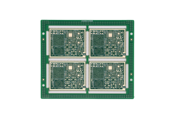
-5G Base Stations (AAU/CU/DU)
•AAU Antenna Boards: 12-layer PTFE/FR-4 hybrid PCBs with 0.13mm blind vias enable 128-channel Massive MIMO, expanding coverage radius by 23% in Huawei’s deployments .
•Baseband Processing Units: 18-layer HDI boards with 30μm traces support PCIe 5.0 (32 GT/s), reducing data latency to <1ms .
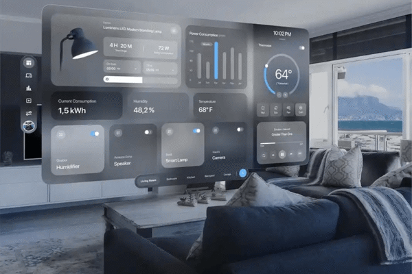
– Edge AI & IoT Gateways
•Multi-Frequency Isolation: Guard-ring shielded zones (0.3mm Cu barriers) suppress cross-band crosstalk to < -80dB, enabling concurrent 5G/Wi-Fi 6 operation .
•Low-Power Design: Polyimide flex-rigid stacks cut gateway power consumption by 15% for solar-powered sites .
-Mission-Critical Medical/Industrial Systems
•CT Scanner Control Boards: 10-layer PCBs with OSP surface finish boost SNR to 90dB (vs. 75dB in 8-layer designs), eliminating imaging noise for FDA-cleared devices .
•Robot Servo Controllers: Symmetrical stackups with Tg 180°C laminates ensure operation from -40°C to 125°C .
Table: Performance Benchmarks of 5G-Optimized PCBs
| Application | PCB Technology | Performance Gain | Validation |
| 5G Macro Base Station | 12-layer PTFE hybrid | 23% coverage radius increase | Field test @28GHz |
| Medical Imaging | 10-layer HDI + OSP finish | 90dB SNR (15dB improvement) | FDA certification |
| AI Edge Gateway | Guard rings + flex-rigid | 98% device connection reliability | Industrial deployment |
The Future: 6G Readiness & Sustainable Innovation
•THz-Frequency Materials: BaTiO₃ nano-ceramics (Dk=15) for 140 GHz adaptive beamforming .
•AI-Driven Dk Adjustment: Real-time dielectric constant tuning for dynamic spectrum sharing .
•Eco-Conscious Manufacturing: Halogen-free laminates with 95% recyclable content, cutting carbon footprint by 30% .
Why Partner with SysPCB for 5G PCBs?
We deliver certified, high-reliability PCBs for 5G’s most demanding applications:
– Material Science Expertise: Rogers/Megtron laminates tailored for mmWave stability.
–Any-Layer mSAP: 30/30μm trace/space for 0.3mm CSP fanouts.
–Thermal Mastery: Cu coin embedding and AlN substrates dissipating 15W/cm².
–Military-Grade Testing: 1000hr 85°C/85% RH aging + 5000 thermal cycles .
“In the 5G PCB era, your PCB isn’t just a carrier—it’s the foundation of signal integrity, thermal resilience, and system reliability. Every micron of copper, every laminate choice, defines network performance.”
Engineered for Tomorrow’s Networks. Built for Today’s Challenges.
→ [Download Our 5G PCB Design Guidelines]
→ [Request a Signal Integrity Simulation]
→ [Explore Certified 5G AAU Reference Designs]