With the rapid development of new energy vehicles, industrial automation, and data centers, the design quality of power PCB, as the “heart” of electronic systems, directly affects equipment stability and energy efficiency. This article deeply analyzes the key technologies and practical strategies of power PCB from core design principles, thermal management technology to industry application scenarios.
Table of Contents
1、 Core principles of power PCB design
1. Collaborative layout of power layer and geological layer
-The power layer and formation should adopt adjacent stacked structures with a spacing of ≤ 3mil to enhance coupling capacitance (typical value 0.5nF/cm ²) and reduce power impedance by 40%.
-A multi power system needs to divide the power supply area to avoid signal lines crossing the divided wiring, which may cause the return path to break and cause EMI problems.

2. Precise configuration of decoupling capacitors
-The decoupling capacitor should be closely attached to the chip power pin (spacing ≤ 2mm), forming a minimum closed loop of “power capacitor ground” to suppress high-frequency noise.
-For different frequency bands of noise, a combination of 0.1 μ F (high-frequency filtering) and 10 μ F (low-frequency filtering) capacitors is required to cover the frequency range of 1MHz-100MHz.
2、 Innovative Practice of Thermal Management Technology
1. Copper layer thickness and optimization of heat dissipation path
-It is recommended to use 2-4oz thick copper for high current paths (such as MOS transistors and rectifier bridges), which can increase the current carrying capacity by more than 50%. At the same time, heat is conducted to the inner ground plane through a heat dissipation hole array (≥ 10/cm ²).
-Copper based heat dissipation channel design: A bare copper area is set below the heating element, combined with thermal conductive adhesive (thermal resistance ≤ 5 ℃/W) to achieve rapid heat dissipation, which can reduce the temperature rise of MOS tubes by 15 ℃.
2. Thermal simulation and dynamic temperature control
-Use CFD thermal simulation tools to predict hotspot distribution (error ≤ 2 ℃), optimize heat dissipation hole layout and copper foil coverage (recommended ≥ 85%).
-Integrating temperature sensors and intelligent control modules, dynamically adjusting heat dissipation strategies, and improving system energy efficiency by 15%.
3、 EMC and Signal Integrity Assurance
1. Layered shielding and signal isolation
-The high-frequency signal line adopts a “sandwich” structure (with ground planes on both sides), and a shielded ground wire is added to the outer layer of sensitive signals (such as clock lines) to reduce crosstalk by 30%.
-Strong and weak current zoning design: The distance between high-voltage lines (such as AC/DC input) and low-voltage signal lines is ≥ 6.4mm, and a grounding copper strip is set at the edge of the board to prevent edge radiation.

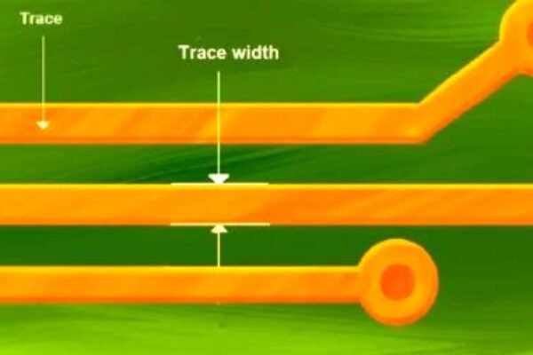
2. Impedance control and wiring rules
-The width of the power supply main line is designed according to the current carrying capacity (such as 3A/mm ² @ 2oz copper thickness) to avoid local overheating caused by sudden changes in line width.
-Differential signal lines are prioritized to ensure equal length (with an error of ± 0.05mm), and the length is adjusted using serpentine routing to reduce timing deviation.
4、 Industry application and reliability verification
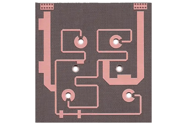
1. New energy vehicle power module
-Adopting ceramic substrate (thermal conductivity ≥ 170W/m · K) and liquid cooled flow channel design, the peak temperature of IGBT module has been reduced from 135 ℃ to 98 ℃, and has passed AEC-Q200 vehicle specification certification.
2. Industrial servo drive system
-Six layer laminated architecture (TOP-GND Signal PWR-GND-BOTTOM), combined with star grounding and π – type filter, passed IEC 61000-4-5 surge test.
Reliability testing standards:
-Thermal cycle test (-40 ℃~125 ℃/1000 times): Resistance change ≤ 2%
-Salt spray test (5% NaCl/48h): Copper foil corrosion rate ≤ 5%
If you need customized power PCB solutions, please feel free to contact our engineering team!