Short circuits between VCC (positive terminal of power supply) and GND (ground) are common and serious problems in PCB (printed circuit board) or electronic circuits, which may cause power short circuits, component burnout, and even pose safety risks. The following is a systematic method for troubleshooting short circuit points:
Table of Contents
1、 Safety preparation before investigation
1. Cut off the power supply: Avoid operating in a live state to prevent the expansion of short circuits or the risk of electric shock.
2. Remove sensitive components: Remove chips and modules (such as MCU and FPGA) that are susceptible to short circuits to prevent secondary damage.
3. Check the power specifications: Confirm whether the power voltage and current are normal, and overvoltage or overcurrent may be the cause of short circuit.

2、 Visual inspection method (applicable to obvious short circuits)
1. Visual observation
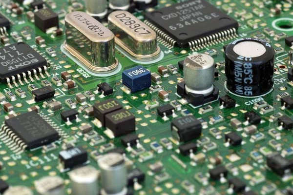
-Check the surface of the PCB for burn marks (such as blackening, blistering), solder pad connections, and foreign objects (such as solder slag and copper shavings).
-Focus on the power input terminal, high current path (such as near the power chip), and high-frequency part (such as switching power supply).
2. Touch check (after power failure)
-Lightly touch the suspicious component or solder joint to check for looseness, virtual soldering, or abnormal temperature (short-circuit points may become hot due to continuous heating).
3、 Resistance measurement method (preliminary positioning)
1. Use a multimeter
-Set the multimeter to “diode mode” or “low resistance mode” and measure the resistance between VCC and GND.
-Normal situation: The resistance value should be close to infinity (M Ω level);
-Short circuit situation: The resistance value is close to 0 Ω (usually<10 Ω), or the multimeter emits a beep sound (diode trigger threshold is about 0.3V).
2. Segmented measurement
-If there are multiple power sources (such as 3.3V, 5V, 12V) on the PCB, it is necessary to disconnect each power network separately and investigate the short-circuit area segment by segment.
-For example, after disconnecting the 3.3V power supply, the short circuit disappears, indicating that the short circuit point is in the 3.3V network.
4、 Voltage division method (applicable to low voltage short circuits)
1. Principle
-Connect a current limiting resistor (such as 100 Ω/2W) in series between VCC and GND, connect a low voltage (such as 3V), and use the voltage divider characteristics of the short-circuit point to locate it.
2. Operation steps
-Connect the circuit according to the following diagram:
| [Positive pole of power supply] → [Current limiting resistor] → [VCC] – Short circuit point – [GND] → [Negative pole of power supply] |
-Measure the voltage at each test point with a multimeter:
-The voltage before the short-circuit point is close to the power supply voltage (such as 3V);
-The voltage after the short-circuit point is close to 0V.
-Measure point by point along the current path, and the voltage jump point is the location of the short circuit.
5、 Burning method (suitable for stubborn short circuits)
1. Principle
-Heat up the short-circuit point with a small current (about 100mA), and use an infrared thermal imager or thermal paper to detect the hot spot.
2. Operation steps
-Power off operation: Remove all ICs from the PCB to avoid burning out.
-Connect to a constant current source: Supply power to the short-circuit network through an adjustable power supply (such as 3V/100mA) for 10-30 seconds.
-Detecting hotspots:
-Use an infrared thermal imaging device to directly observe the temperature distribution on the surface of the PCB;
-Or stick thermal paper (which changes color when exposed to heat), and the color changing area is the short-circuit point.
3. Precautions
-The current needs to be strictly controlled to avoid excessive damage to the PCB.
-The operation time should not be too long to prevent overheating of the components.
6、 Isolation method (gradual elimination)
1. Remove parallel components
-Disconnect the components connected to VCC or GND one by one (such as capacitors and diodes), measure the resistance of each component, and when the resistance returns to normal, the newly removed component is the short-circuit source.
2. Flying line method
-If you suspect a short circuit in the inner wiring of the PCB, you can cut off the suspicious circuit and connect the normal part with a flying wire to verify if it has been restored.
7、 IC short circuit troubleshooting
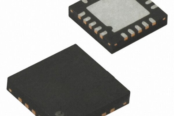
1. IC internal short circuit
-Internal breakdown of certain ICs (such as power management chips) may cause VCC-GND short circuits.
-Troubleshooting method:
-After removing the suspicious IC, measure the resistance. If the resistance value is restored, the IC will be damaged;
-When using the burning method, the surface temperature of the IC increases abnormally (>60 ℃).
2. Parasitic capacitance/ESD protection diode short circuit
-The power pin of high-frequency IC may be short circuited to ground through parasitic capacitance or ESD diode, and the signal waveform needs to be observed with an oscilloscope.
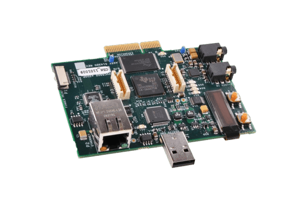
8、 PCB manufacturing defect investigation
1. Inner short circuit
-The short circuit of copper foil in the inner layer of multi-layer PCB is difficult to observe directly, and the following methods need to be combined:
-X-ray inspection: Check whether there is copper foil adhesion in the inner layer wiring through X-ray equipment;
-Chemical corrosion method: Corrosion the PCB layer by layer, exposing the inner layer for inspection (destructive method, only applicable to scrapped boards).
2. Via/pad issues
-Through holes, solder pads, and inner layer short circuits: Use flying wires to bypass suspicious through holes and verify if they have been restored.
9、 Preventive measures
1. Design phase
-Avoid sharp angle wiring between power supply and ground plane to reduce the risk of short circuit.
-Add a 0 Ω resistor or fuse to the critical power network (such as the main power supply) for easy short-circuit isolation.
2. Production stage
-Add Flying Probe or Automatic Optical Inspection (AOI) during PCB manufacturing to detect short circuit defects.
3. Debugging phase
-Before powering on for the first time, be sure to measure the VCC-GND resistance to confirm that there is no short circuit.
10、 Summary
To troubleshoot VCC-GND short circuits, the principle of “safety first, location later, simplicity first, complexity later” should be followed:
1. Preliminary inspection: visual observation, resistance measurement;
2. Segmented positioning: voltage division method and isolation method to narrow down the scope;
3. Accurate positioning: burning method, thermal imaging to lock the short-circuit point;
4. Special circumstances: IC internal short circuit needs to be dismantled for verification, and PCB internal short circuit needs to rely on professional equipment.
Through systematic methods, most short-circuit problems can be quickly resolved. If still unable to locate, it is recommended to seek assistance from professional testing equipment (such as online tester ICT) or PCB manufacturers.
Get your exclusive quote immediately: fill out the form or send an email directly.As a professional PCB manufacturer for hobbyist , we will provide you with a quote service within 24 hours. Enjoy free DFM optimization and a 10% discount on SMT patches for your first order!