In 5G base stations, vehicle mounted radars, and satellite communication systems, microstrip lines serve as the core carrier for signal transmission, and their design accuracy directly determines the performance boundary of high-frequency circuits. This article starts from fundamental theories and combines materials engineering and manufacturing processes to analyze the key technological breakthroughs of microstrip lines in millimeter wave scenarios.
Table of Contents
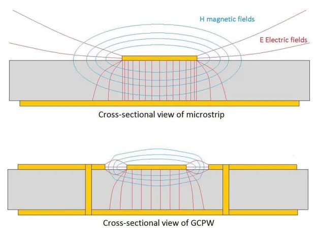
1、 Basic characteristics and electromagnetic field distribution of microstrip line structure
A microstrip line is composed of a surface conductor strip and an adjacent ground plane, and its electromagnetic field is distributed between the dielectric substrate and the air layer. At the 28GHz frequency band, the effective dielectric constant of the Rogers RO4350B substrate’s microstrip line can be precisely controlled in the range of 3.42-3.54, reducing path loss by about 40% compared to traditional strip line structures. Through finite element simulation, it can be found that when the linewidth is 0.76mm (substrate thickness 0.508mm), the characteristic impedance stabilizes at 50 Ω± 1 Ω, meeting the phase consistency requirements of 5G Massive MIMO antennas.

2、 Key points of process control in millimeter wave frequency band
1. Substrate selection and dielectric stability
In the application of 77GHz vehicle radar, the combination of aluminum nitride ceramic substrate (thermal conductivity ≥ 170W/m · K) and low roughness copper foil (RTF ≤ 1.2 μ m) can control signal loss within 0.03dB/mm. The fluctuation of substrate thickness should be ≤ ± 2% to prevent impedance mismatch caused by effective dielectric constant drift.
2. Precision machining and deformation control
Using laser direct imaging (LDI) technology, the line width processing accuracy reaches ± 5 μ m, ensuring the wavelength/20 accuracy requirement (about 0.52mm) in the 28GHz frequency band. During the copper foil etching process, a dynamic compensation algorithm is introduced to counteract the trapezoidal cross-sectional effect caused by side etching, reducing high-frequency resistance fluctuations to within 3%.
3、 Reliability verification in complex environments
1. Multi physics field coupling simulation
Through the collaborative simulation of HFSS and Icepak, the performance changes of 77GHz microstrip lines can be predicted under the operating conditions of -40 ℃~125 ℃
-When the temperature rises by 10 ℃, the phase shift is ≤ 0.5 °/cm
-Impedance fluctuation<1% under 5G mechanical vibration conditions
2. Practical verification of vehicle mounted radar
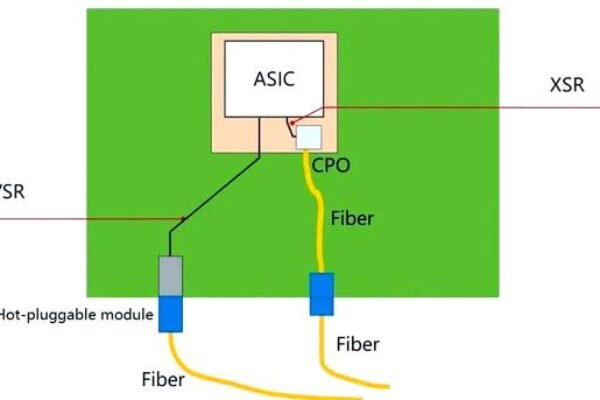
A 77GHz forward radar module adopts a four layer mixed voltage structure (RO4350B+FR4), and achieves impedance matching between microstrip lines and MMIC chips through grounded coplanar waveguide transition design. Actual testing shows:
-Insertion loss: 0.4dB/ cm@76-81GHz
-Return loss:<-20dB
-Parameter drift<2% after high-temperature aging (150 ℃/1000h)
4、 Breakthrough in performance brought by new materials
1. Application of Liquid Crystal Polymer (LCP) substrate
In satellite Ka band (26.5-40GHz) communication systems, the dielectric loss (Df=0.002) and thermal expansion coefficient (CTE=17ppm/℃) characteristics of LCP substrate increase the antenna efficiency of microstrip line array to 78%, which is 15 percentage points higher than PTFE substrate. The flexible LCP circuit can withstand 50000 bending cycles, which meets the curved layout requirements of phased array antennas.
2. Evolution of 3D integration technology
A three-dimensional microstrip structure based on through silicon via (TSV) enables vertical signal transmission in the 38GHz frequency band, with a 60% reduction in path length. Through wafer level packaging integration, a single 5G millimeter wave module can accommodate a 256 channel microstrip line array, with a power density increased to 8W/cm ².
From material innovation to continuous evolution of manufacturing processes, microstrip line technology is redefining the performance limits of high-frequency PCBs. In the new field of 6G terahertz communication and quantum radar, designers need to establish a new balance model between dielectric accuracy, thermodynamic stability, and cost control.