In PCB design, reverse power connection is a common but potentially serious error. When the polarity of the power supply is reversed, it may cause components in the circuit to burn out, the system to malfunction, and even lead to safety accidents. Therefore, designing an effective power reverse protection circuit is an indispensable part of PCB design. This article will provide a detailed introduction to common power reverse protection schemes, design points, and precautions in practical applications.
Table of Contents
Ⅰ. The hazards and protection requirements of reverse power supply connection
Reverse connection of the power supply can cause reverse current flow, which may lead to the following issues:
1. Component damage: Reverse voltage may breakdown diodes, transistors, integrated circuits, and other components, causing permanent damage.
2. System failure: Reverse connection may cause the circuit to malfunction or even cause a short circuit, affecting the stability of the entire system.
3. Safety risk: In high-power or high-voltage scenarios, reverse connection may cause fire or electric shock risks.
Therefore, the core goal of designing a power reverse protection circuit is to quickly cut off the circuit or adjust the current direction when the power polarity is reversed, ensuring the safety of the subsequent circuit.
Ⅱ. Common power reverse protection schemes
1. Diode anti reverse circuit
Principle: By utilizing the unidirectional conductivity of diodes, when the power supply is positively connected, the diode conducts, allowing current to pass through; When the power supply is reversed, the diode cuts off and blocks the current.
advantage:
-The circuit structure is simple and the cost is low.
-No need for additional control circuits, high reliability.
Disadvantages:
-The diode has a voltage drop (about 0.7V for silicon tubes and about 0.2V for Schottky diodes), which can cause a decrease in the input voltage of the subsequent circuit.
-In high current scenarios, the power consumption of diodes is relatively high, which may lead to heating problems.
Applicable scenarios:
-Low power, low current circuits (such as portable devices, sensor modules).
-Applications that are cost sensitive and allow for a certain pressure drop.
Design points:
-Choose the appropriate diode type: Based on current and voltage drop requirements, prioritize Schottky diodes to reduce power consumption.
-Calculate the power consumption of the diode: Ensure that the rated current and power of the diode can meet the circuit requirements, and add heat dissipation measures if necessary.
-Pay attention to reverse withstand voltage: The reverse withstand voltage of the diode should be greater than the maximum reverse voltage that the power supply may experience.
2. MOS anti reverse circuit
Principle: By utilizing the switching characteristics of MOS transistors and controlling the gate voltage, the circuit can be turned on and off. When the power supply is connected positively, the MOS transistor conducts; When the power supply is reversed, the MOS transistor is turned off.
advantage:
-The conduction voltage drop is extremely low (milliohm level), suitable for high current and high power scenarios.
-Intelligent protection can be achieved through control circuits, such as overcurrent and overheating protection.
Disadvantages:
-The circuit complexity is high, and it is necessary to design a suitable driving circuit.
-The selection and layout of MOS transistors need to be cautious to avoid the influence of parasitic effects.
Applicable scenarios:
-High current, high-power circuits (such as automotive electronics, industrial equipment).
-Applications that require high efficiency and stability.
Design points:
-Choose the appropriate MOS transistor type: NMOS or PMOS, based on the circuit structure and control requirements.
-Design driving circuit: Ensure that the gate voltage can reliably control the conduction and turn off of the MOS transistor to avoid misoperation.
-Consider parasitic effects: During layout, try to shorten the source and drain routing of MOS transistors to reduce the impact of parasitic inductance and capacitance.
3. Bridge rectifier circuit
Principle: Through a bridge structure composed of four diodes, current is forced to flow in one direction, and the output voltage direction remains constant regardless of the polarity of the power supply.
advantage:
-It can adapt to any connection of power polarity without the need for additional polarity detection circuits.
-Stable output voltage, suitable for scenarios that require bidirectional power supply.
Disadvantages:
-There is a voltage drop of about 1.4V between two diodes, resulting in a decrease in efficiency.
-The circuit complexity is high and occupies a large PCB space.
Applicable scenarios:
-Devices that require compatibility with positive and negative polarity DC power sources (such as chargers, universal interfaces).
-A circuit that is insensitive to power polarity.
Design points:
-Choose diodes with low voltage drop, such as Schottky diodes, to reduce power consumption.
-Optimize layout: reduce the routing length between diodes and decrease parasitic inductance.
-Add filtering capacitors: Improve the ripple of the output voltage.
4. Specialized protection chip
Principle: A dedicated chip that integrates multiple functions such as power reverse protection, overcurrent protection, and overheating protection, providing comprehensive protection.
advantage:
-High integration, comprehensive functionality, and reduced number of peripheral components.
-Fast response speed and high protection accuracy.
Disadvantages:
-High cost, suitable for scenarios with extremely high reliability requirements.
-Accurate peripheral circuit design is required based on chip specifications.
Applicable scenarios:
-High end equipment (such as medical electronics, aerospace equipment).
-A circuit with strict requirements for protection functions.
Design points:
-Choose the appropriate chip model: Select based on power supply voltage, current, and protection requirements.
-Follow the design requirements of the chip specification sheet, including the selection, layout, and wiring of peripheral components.
-Conduct sufficient testing and verification to ensure that the protection function of the chip is normal under various working conditions.
Ⅲ.Key considerations in PCB design
1. Component selection and layout
-Component selection: Select appropriate diodes, MOSFETs, or protection chips based on the operating voltage, current, and protection requirements of the circuit. Note that the rated parameters of the components (such as reverse withstand voltage, on resistance, power consumption) should meet the circuit requirements.
-Layout strategy:
-Place protective components (such as diodes and MOSFETs) near the power input port to shorten the current path and reduce parasitic inductance.
-For MOS transistors, the gate drive circuit should be laid out separately from the power circuit to avoid interference.
-Ensure that there is sufficient space for heat dissipation components (such as heat sinks, heat sinks) to ensure their stability under high currents.
2. Wiring design
-Power line width: Design a sufficiently wide power line based on the operating current of the circuit to reduce line resistance and voltage drop.
-Ground plan design: Using a large area of ground plane to provide a low impedance return path and reduce electromagnetic interference (EMI).
-Signal isolation: Isolate the protective circuit from the sensitive signal circuit to avoid mutual interference.
3. Testing and Verification
-Functional testing: Simulate the reverse connection of the power supply to verify whether the protection circuit can cut off the circuit or adjust the current direction in a timely manner.
-Reliability testing: Conduct environmental tests such as high temperature, low temperature, and humidity to ensure the stability of the protective circuit under extreme conditions.
-EMC testing: Testing the electromagnetic compatibility of the circuit to ensure that the protective circuit does not interfere with other modules.
Ⅳ. Practical application cases
Case 1: Anti reverse diode design for portable devices
A portable device is powered by a 3.7V lithium battery, with design requirements for low cost and small size. Adopting diode anti reverse circuit and selecting Schottky diode (such as SS34), its voltage drop is 0.3V, which can meet the circuit requirements. The diode is placed near the power input port, with the positive terminal connected to the positive terminal of the battery and the negative terminal connected to the rear circuit. This design is simple and reliable, suitable for low current scenarios.
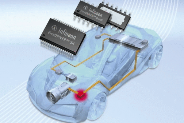
Case 2: MOS tube anti reverse connection design for automotive electronics
A certain automotive electronic device needs to withstand a wide voltage input (9-36V) and provide high current output. Using PMOS transistors (such as IPD80P03P4) as protective elements, their conduction and turn off are controlled by a gate drive circuit. The source of the PMOS transistor is connected to the positive pole of the power supply, the drain is connected to the downstream circuit, and the gate is biased through a voltage divider resistor and a voltage regulator diode. This design can effectively prevent reverse connection of the power supply, while reducing voltage drop and improving efficiency.
Case 3: Bridge rectifier circuit design with universal interface
A certain charger needs to be compatible with positive and negative polarity DC power supply, using a bridge rectifier circuit. Choose Schottky diodes (such as MBR20100CT) with a voltage drop of 0.5V, which can meet efficiency requirements. Add a filtering capacitor (such as 1000 μ F) to the output terminal of the bridge rectifier circuit to improve the stability of the output voltage. This design can adapt to power inputs of any polarity and is suitable for universal interfaces.
Ⅴ.Summary
Power reverse protection is an essential part of PCB design, which directly affects the reliability and safety of the circuit. According to the actual needs of the circuit, selecting appropriate protection schemes (such as diodes, MOS transistors, bridge rectifiers, or dedicated chips), and paying attention to component selection, layout, and wiring in PCB design can effectively prevent the harm caused by power reverse connection. Through reasonable design and sufficient testing verification, the stable operation of the circuit under various working conditions can be ensured, improving the competitiveness and user experience of the product.
In practical applications, optimization should also be based on specific scenarios, such as selecting high-temperature resistant components in high temperature environments and strengthening moisture-proof measures in high humidity environments. At the same time, we pay attention to industry standards and emerging technologies (such as the application of GaN and SiC devices in power reverse protection), continuously improving our design level to meet the ever-changing market demands.
Get your exclusive quote immediately: fill out the form or send an email directly.As a professional PCB manufacturer for hobbyist , we will provide you with a quote service within 24 hours. Enjoy free DFM optimization and a 10% discount on SMT patches for your first order!