The manufacturing process of PCBA (Printed Circuit Board Assembly) is complex, involving multiple steps such as solder paste printing, component mounting, soldering, testing, etc. Each step may result in defects due to factors such as equipment, materials, and process parameters. The following are common PCBA manufacturing defect classifications and specific explanations:
Table of Contents
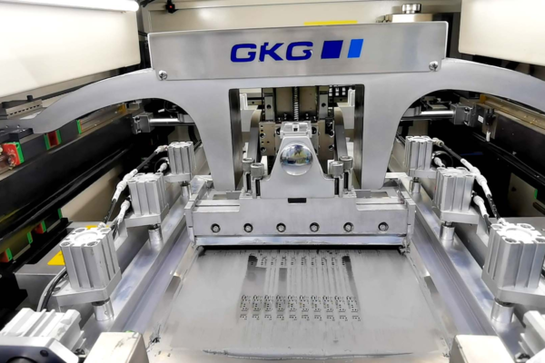
1、 Solder paste printing defects
Solder paste printing is the first critical step in PCBA manufacturing, and defects mainly stem from improper steel mesh, solder paste characteristics, or printing parameters:
1. Insufficient Solder
-Performance: Insufficient amount of solder paste on the solder pad, resulting in smaller or virtual solder joints after soldering.
-Reason: Steel mesh holes are too small/blocked, solder paste viscosity is too high, and printing pressure is insufficient.

2. Excess Solder
-Performance: Excessive solder paste on the solder pads may cause bridging (short circuit) between adjacent solder joints.
-Reason: The steel mesh has too many openings, the printing pressure is too high, and the viscosity of the solder paste is too low.
3. Solder Paste Misalignment
-Performance: The solder paste does not completely cover the solder pads and deviates from the PCB substrate or adjacent solder pads.
-Reason: Inaccurate positioning of steel mesh and PCB, PCB warping, and insufficient accuracy of printing platform.
4. Solder Paste Slump
-Performance: After solder paste printing, it diffuses due to gravity or high temperature, causing adjacent solder paste pads to be connected.
-Reason: The proportion of flux in the solder paste is too high, the ambient temperature is too high, and the post printing storage time is too long.
5. Solder Paste Void
-Performance: There are bubbles or unfilled areas inside the solder paste, which may form solder joint voids after welding.
-Reason: Insufficient mixing of solder paste, impurities in the steel mesh openings, and too fast printing speed.
2、 Component mounting defects
The placement process relies on the accuracy of the placement machine, and defects are often related to equipment parameters, component/PCB status:
1. Component misalignment

-Performance: Component pins are not aligned with the solder pads, partially or completely deviating.
-Reason: Wear of the suction nozzle of the SMT machine, incorrect identification of component dimensions, and blurred PCB positioning marks (Mark points).
2. Missing Components
-Performance: The position where the components should be mounted is empty.
-Reason: The feeder is stuck, the suction nozzle is not holding onto the component (such as the component being too light or the suction nozzle being blocked), and the program is missing the component.
3. Wrong Component
-Performance: The model and specifications of the mounted components do not match the design (such as incorrect resistance and capacitance values).
-Reason: Material mixing, incorrect program call of surface mount machine, malfunction of component recognition system (such as misjudgment of components with similar appearance).
4. Polarity Reverse
-Performance: Polarized components (such as diodes, capacitors, ICs) have their positive and negative poles opposite to the PCB markings.
-Reason: incorrect polarity recognition of the surface mount machine, blurry polarity identification of PCB silk screen printing, and incorrect material direction in the feeder.
5. Floating height (Tombstoning/Lifting)
-Performance: Chip components (such as resistors and capacitors) have one end raised and the other end soldered onto a solder pad, resembling a tombstone.
-Reason: Different sizes of solder pads on both ends, uneven amount of solder paste, and significant temperature difference between the two ends during soldering.
3、 Welding defects (reflow soldering/wave soldering)
Welding is the core process of permanently connecting components to PCBs, and defects are closely related to temperature curves, solder paste quality, etc
1. Cold Solder Joint
-Performance: The surface of the solder joints is rough and dull, and the connection between the components and the solder pads is not firm, prone to detachment or poor conductivity.
-Reason: Low soldering temperature or insufficient time, pad/pin oxidation, solder paste and flux failure.
2. Bridging
-Performance: Adjacent solder joints are connected by soldering, resulting in a short circuit.
-Reason: Excessive solder paste, component displacement, and strong solder fluidity during soldering (such as high temperature).
3. Solder Void
-Performance: There are bubbles or indentations inside or on the surface of the solder joint, which affect conductivity and mechanical strength.
-Reason: Failure to timely discharge volatile substances from solder paste, contamination of solder pads/pins, and unreasonable soldering temperature curve.

4. Solder Ball
-Performance: There are small solder particles on the surface of the PCB or around the components, which may cause short circuits.
-Reason: Solder paste collapse, excessive amount of solder paste, and sudden temperature rise during soldering causing solder splatter.
5. Overheating
-Performance: The solder joints are charred black, and the components (especially plastic encapsulated ICs) are deformed and cracked.
-Reason: Welding temperature is too high or time is too long, and protective measures have not been taken for thermal sensitive components.
6. Poor wetting (Non Wetting)
-Performance: Solder does not completely cover the solder pads or component pins, forming a “spherical” accumulation.
-Reason: pad/pin oxidation or contamination, insufficient flux activity, insufficient soldering temperature.
4、 Other defects
1. PCB damage
-Including PCB cracking, scratching, deformation, copper foil detachment, etc., they are often caused by improper handling, excessive equipment clamping force, and uneven thermal stress during welding.
2. Excessive residual flux
-After soldering, there is a large amount of residual flux on the surface of the PCB, which may corrode the components or affect the appearance, due to incomplete volatilization of flux or lack of cleaning process.
3. Mechanical damage
-If the pins of the components are deformed or broken, it is often caused by excessive pressure from the suction nozzle of the surface mount machine or manual operation errors (such as excessive force when inserting and removing components).
Summarize
The prevention of PCBA manufacturing defects requires a combination of process optimization (such as calibrating equipment parameters, optimizing temperature curves), quality inspection (such as AOI automatic optical inspection, X-ray inspection), and material management (such as ensuring component and solder paste quality). Different defects may be interrelated (such as solder paste offset causing bridging), so it is necessary to control the entire process to reduce the defect rate.
Get your exclusive quote immediately: fill out the form or send an email directly.As a professional PCB manufacturer for hobbyist , we will provide you with a quote service within 24 hours. Enjoy free DFM optimization and a 10% discount on SMT patches for your first order!