> Statistics show capacitor failure accounts for over 60% of PCB malfunctions—with electrolytic types being the predominant culprit in voltage regulation circuits .
As global demand for high-reliability electronics surges, capacitor-related PCB failures remain a primary pain point for OEMs. From industrial controllers to automotive ECUs, understanding capacitor degradation mechanisms and mastering inspection protocols is critical for minimizing downtime. This guide details field-proven methodologies to diagnose and resolve capacitor failures, enhancing your product’s operational lifespan.
Table of Contents
1. Core Failure Modes: From Degradation to Catastrophe
Capacitor failures manifest in four primary forms, each with distinct symptoms:
– Capacity Fade
Electrolytic capacitors lose electrolyte due to vaporization, causing capacitance to drop below 80% of nominal value. Result: power supply ripple increases, triggering logic errors or boot failures (common in aging motherboards).
– Leakage/Short Circuits
Contaminated dielectrics or dendrite growth create current leakage paths. Severe cases cause thermal runaway, evidenced by bulging casings or electrolyte leakage (e.g., 1000μF/350V capacitors near heat sinks).
– ESR Increase
Equivalent Series Resistance rises with oxide layer deterioration, degrading filtering efficiency. Critical in switch-mode power supplies where ESR > 2Ω causes output instability.
– Open Circuits
Mechanical stress fractures internal connections, cutting off current flow. Common in surface-mount MLCCs subjected to board flexing.
High-Risk Locations: Prioritize capacitors within 15mm of heat sources (e.g., voltage regulators, power transistors). For every 10°C above rated temperature, lifespan halves per the 8°C Rule.
2. Diagnostic Protocol: Systematic Fault Isolation
Stage 1: Visual-Tactile Inspection
– Bulging/Leakage Check: Examine capacitor tops for convex deformation or electrolyte residue (indicating pressure vent activation).
– Thermal Scan: Power on board for 5 minutes. Finger-touch capacitors—temperatures >85°C indicate excessive leakage current.

Stage 2: Electrical Testing
– In-Circuit Capacitance/ESR:
Use LCR meter at rated frequency (e.g., 100kHz for decoupling caps). Tolerance thresholds:
– Capacitance: ±20% of nominal value
– ESR: >150% of datasheet specification
– Leakage Current Test:
Apply 80% of rated DC voltage. Acceptable leakage: ≤0.01CV μA (C=capacitance, V=voltage) after 2 minutes.
Stage 3: Advanced Failure Analysis
– Vector Network Analysis:
Detect dielectric absorption anomalies in high-frequency RF circuits.
– X-Ray Imaging:
Identify internal electrode separation in BGA-packaged MLCCs.
3. Targeted Repair Techniques
3.1 Electrolytic Capacitor Replacement
– Desoldering: Preheat board to 150°C to avoid pad lifting. Use vacuum tweezers for through-hole types.
– Selection Criteria:
– Choose 105°C-rated capacitors over 85°C variants (2x lifespan at 65°C ambient)
– Low-ESR series (e.g., Rubycon ZLG, Panasonic FM) for switching supplies.
3.2 MLCC Crack Mitigation
– Mechanical Reinforcement: Apply silicone gel coating to absorb board flex stress
– Layout Optimization: Position ≥1mm from board edges and mounting screws.
3.3 Power Supply Short-Circuit Localization
– Current Injection Method:
1. Connect adjustable DC supply (0-30V/3A) to shorted rail
2. Gradually increase current from 100mA
3. Thermal camera identifies overheating components within 30 seconds.
4. Preventive Maintenance: Extending Service Life
4.1 Environmental Controls
– Humidity Management: Maintain RH <60% to prevent tin whisker growth
– Dust Mitigation: Conformal coating or IP54 enclosures in industrial settings.
4.2 Circuit Design Best Practices
– Derating Principles:
– Voltage: Operate at ≤75% of rating
– Ripple Current: Limit to 70% of maximum
– Thermal Design:
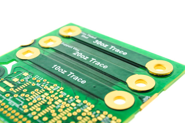
– 2oz copper planes under high-current capacitors
– Thermal vias to inner layers (0.3mm diameter, 1mm spacing).
4.3 Predictive Replacement
– Lifetime Modeling: Replace electrolytic capacitors after 30,000 hours at 65°C ambient
– Field Monitoring: IoT-enabled capacitance sensors transmitting real-time ESR data.
5. Industry Case Studies
Medical X-Ray Power Supply
– Failure Mode: Intermittent shutdown with electrolyte leakage
– Root Cause: 1000μF/350V capacitor adjacent to rectifier heatsink (ambient 110°C)
– Solution:
– Replaced with 105°C-rated low-ESR capacitor
– Added thermal gap pad to redirect heat
– Result: 5+ years failure-free operation.

Automotive ECU Voltage Fluctuation
– Symptoms: Engine stalling during cold starts
– Diagnosis: Capacitance drop (2200μF → 800μF) in ignition circuit
– Corrective Action:
– Switched to polymer aluminum capacitors (-55°C to 125°C range)
– Implemented conformal coating against condensation
– Outcome: Zero field returns over 3 winters.
Conclusion: Building Failure-Immune Electronics
Capacitor reliability hinges on three pillars: proactive design, precision diagnostics, and preventive maintenance. As industrial electronics evolve toward 200°C junction temperatures (e.g., SiC-based systems), only manufacturers mastering these disciplines will deliver mission-critical durability.
>SysPCB Solutions provides:
> – Free Capacitor Health Audits: Submit board photos + symptom description for failure analysis report within 24h
> – High-Reliability Kits: Military-grade capacitors with 10,000hr @ 125°C lifespan
> – Design for Reliability (DfR): Optimized layouts to reduce capacitor thermal stress by 40%.
Get your exclusive quote immediately: fill out the form or send an email directly.As a professional PCB manufacturer for hobbyist , we will provide you with a quote service within 24 hours. Enjoy free DFM optimization and a 10% discount on SMT patches for your first order!