The performance and appearance quality inspection of PCB components is a key link in ensuring the reliability and functionality of the circuit board, involving multiple dimensions of testing items and standards. The following provides a detailed explanation from two aspects: appearance quality inspection and performance inspection:
Table of Contents
1、 Appearance quality inspection
Appearance inspection mainly involves visual inspection, magnifying glass, or automated equipment (such as AOI automatic optical inspection) to observe whether the surface and structure of the PCB comply with specifications. Common inspection items include:
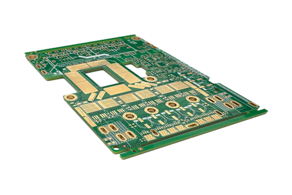
1. Size and structure
-Dimensions: Confirm whether the length, width, and thickness of the PCB comply with the design drawings, whether the edges are flat, and whether there are burrs or gaps.
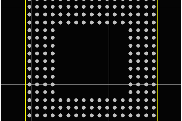
-Hole accuracy: Check whether the position and diameter of the through-hole (installation hole, conductive hole) are correct, whether the hole wall is smooth, and whether there is any deviation or damage.

-Inter layer alignment: For multi-layer boards, it is necessary to check whether the lines on each layer are aligned and there is no obvious offset that may cause a short circuit risk.
2. Surface defects
-Line defects:
-Is there any open circuit, short circuit, uneven thickness or local etching (such as thinning of the circuit) in the circuit.
-Whether the solder pads are intact, free from detachment, oxidation, gaps, or insufficient spacing between solder pads.
-Solder mask (green oil):
-Color uniformity: The surface is free of bubbles, impurities, overspray, or uneven thickness.
-Coverage accuracy: Whether the solder mask completely covers the non solder pad area, whether the solder pad window position is accurate, without offset or obstruction.
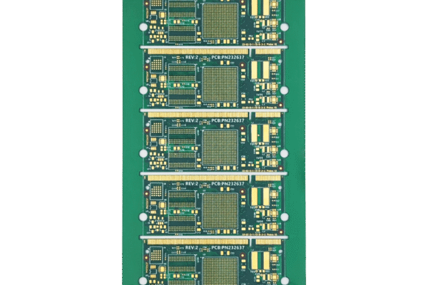
-Character silk screen printing:
-Whether the characters and labels are clear and distinguishable, without blurring, missing strokes or positional deviation, and whether the content (such as PCB component tag numbers and polarity labels) is correct.
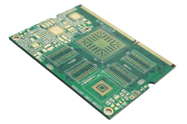
3. Plating and Coating
-Surface treatment layer:
-Gold/silver/nickel layer: uniform thickness, no exposed copper, blackening, peeling or poor adhesion (can be tested by tape).
-Sinking tin/silver layer: The surface is smooth, without oxidation or discoloration.
-Flux residue: The surface is clean and there is no obvious accumulation of flux, oil, or dust.
4. Other structural defects
-Metallized pores (PTH): Whether the pore wall is smooth, whether there are voids, cracks, or coating peeling (can be analyzed by slicing).
–Multi layers board compression: no delamination, bubbles or bursting (especially after heating).
-Installation components (such as connectors and sockets): The welding or crimping position is correct, without looseness, skewness, or mechanical damage.
2、 Performance quality inspection
Performance inspection requires professional equipment to test the electrical characteristics and reliability of the PCB, ensuring that it meets the design functionality and usage environment requirements.
1. Electrical performance testing
-Continuity test:
-Use a flying needle tester or needle bed fixture to check whether the circuit network is conductive, whether there is an open circuit or short circuit.
-Focus on inspecting areas that are difficult to reach manually, such as dense circuits and BGA solder pads.
-Insulation resistance test:
-Measure the insulation resistance between adjacent lines or layers, verify whether it meets the design requirements (such as ≥ 100M Ω), and avoid the risk of leakage.
-Impedance test:
-Measure the characteristic impedance of high-frequency signal lines (such as USB, HDMI, RF lines) to ensure impedance matching (such as 50 Ω/90 Ω) and reduce signal reflection.
-Voltage endurance test:
-Apply high voltage (such as 500V~1000V) to test the withstand voltage capability between lines or layers to prevent breakdown.
2. Reliability testing
-Temperature environment testing:
-High temperature aging: Place the PCB in a high temperature environment (such as 85 ℃) for several hours and observe whether there is delamination, discoloration, or performance drift.
-Cold and hot shock: Cycle between -40 ℃ and 125 ℃ to test the material’s resistance to thermal expansion and contraction, and avoid cracking of solder joints or circuit breakage.

-Moisture resistance test:
-Place in a high humidity environment (such as 85% RH, 85 ℃) for the “85/85 test” to evaluate moisture resistance and insulation stability.
-Mechanical stress testing:
-Vibration/impact testing: Simulate mechanical stress during transportation or use to check the soldering firmness of components and the PCB’s resistance to deformation.
-Bending test: measure the circuit reliability of PCB under a certain degree of bending (such as the bending life of flexible board).
3. Special function verification
-For PCBs with special requirements (such as automotive electronics, medical equipment), additional testing is required:
-Electromagnetic compatibility (EMC): radiation and anti-interference capability.
-Solderability test: Check whether the solder on the solder pad is uniform and has good wetting properties (such as solder adhesion ≥ 95%).
-Coating thickness detection: Metal coating thickness is measured by X-ray fluorescence (XRF) to ensure compliance with standards (such as gold plating ≥ 0.1 μ m).
3、 Inspection standards and tools
1. Industry standards:
-IPC-A-600 (International General PCB Acceptance Standard) specifies the defect acceptance range according to the grades (Class 1-3).
-Internal standards of enterprises, such as Huawei, Apple, etc., require strict customization of PCBs.
2. Common tools:
-Visual tools: magnifying glass (5-10 times), microscope (20-100 times), AOI automatic optical detector.
-Electrical testing equipment: flying needle tester, ICT online tester, LCR bridge, oscilloscope.
-Reliable equipment: constant temperature and humidity chamber, cold and hot shock chamber, vibration table.
4、 Common Defects and Handling
| Defect type | Possible causes | Handling measures |
| Line break | Over etching, drilling damage | Rework, repair or scrap |
| Solder mask bubbles | Uneven temperature/pressure during coating | Adjust process parameters and recoat |
| Pad detachment | Insufficient adhesion between substrate and coating | Optimized pre-treatment (such as degreasing and roughening) |
| Impedance deviation exceeds the standard | Poor control of line width/dielectric thickness | Adjust the plate making process and reproduce |
| Failure of withstand voltage test | Thin or contaminated interlayer insulation layer | Strengthen cleaning and increase insulation layer thickness |
5、 Summary
The quality inspection of PCB components should take into account both visible defects and hidden performance risks, and ensure that each circuit board meets design requirements through standardized processes and professional equipment. For high reliability scenarios such as aerospace and industrial control, it is recommended to use 100% full inspection and non-destructive testing techniques (such as X-ray inspection of multi-layer board internal structures) to minimize defect rates. Regularly updating testing standards and equipment, combined with statistical process control (SPC) analysis of defect trends, to sustainably improve PCB production quality.
Get your exclusive quote immediately: fill out the form or send an email directly.As a professional PCB manufacturer for hobbyist , we will provide you with a quote service within 24 hours. Enjoy free DFM optimization and a 10% discount on SMT patches for your first order!