Table of Contents
Executive Summary
Automotive-grade EMI solutions are critical for ensuring the reliability and performance of modern vehicle electronics. As automobiles evolve into complex electronic systems with advanced driver-assistance systems (ADAS), infotainment systems, and electric powertrains, managing electromagnetic interference (EMI) becomes increasingly challenging. This comprehensive guide explores proven PCB-level strategies for mitigating EMI in automotive applications, including proper layout techniques, component selection, and design methodologies that meet stringent automotive EMC standards such as CISPR 25 Class 5.
1.The Growing EMI Challenge in Automotive Electronics
The rapid electrification and digitalization of vehicles have significantly intensified EMI challenges in automotive environments. Modern cars contain numerous electronic control units (ECUs), high-speed communication networks (CAN FD, Automotive Ethernet), and power-hungry systems that generate and are susceptible to electromagnetic interference. These systems must operate reliably in close proximity without mutual interference while withstanding external electromagnetic disturbances.
The automotive electromagnetic environment is particularly harsh due to the presence of high-power switches, motors, and ignition systems that generate significant noise. Furthermore, the trend toward domain controllers and consolidated ECUs means that multiple systems share the same PCB real estate, increasing the potential for noise coupling. Compliance with international EMC standards like CISPR 25 is not just a regulatory requirement but a necessity for functional safety and reliability.

2.Key PCB-Level EMI Mitigation Strategies
2.1 Optimized Layout and Stackup Design
Proper PCB layout is the first line of defense against EMI in automotive applications. Key considerations include:
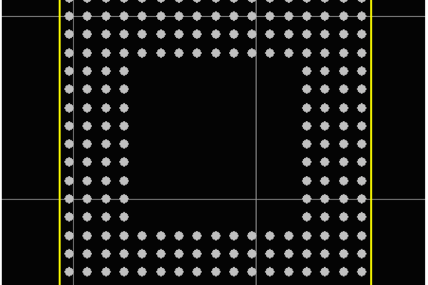
•Multilayer Stackups: Implementing 8-layer PCB designs with dedicated power and ground planes creates low-impedance return paths and reduces electromagnetic emissions. This structure helps contain electromagnetic fields and provides inherent shielding.
•Component Placement: Strategic placement of noise-sensitive components away from potential noise sources minimizes interference. Grouping components by function (analog, digital, power) prevents noise coupling between circuits.
•Ground Plane Integrity: Maintaining uninterrupted ground planes is essential for providing stable reference points and minimizing ground bounce. Proper grounding strategies significantly impact overall EMC performance.
2.2 Careful Component Selection
Choosing appropriate components is crucial for EMI control:
•Semi-Shielded Inductors: New component technologies like Bourns’ SRN5040TA-P Series semi-shielded power inductors with polarity control help minimize magnetic field radiation. Their magnetic-epoxy coating provides effective shielding while maintaining high performance.
•Integrated Power Modules: Devices such as the UCC12051-Q1 isolation modules incorporate transformers and control circuits in compact packages, reducing EMI by minimizing loop areas and providing built-in filtering.
•Automotive-Grade Switching Regulators: Specialized regulators with spread spectrum techniques and optimized switching characteristics significantly reduce EMI at the source.
2.3 Filtering Techniques
Effective filtering is essential for EMI control:
•Front-End Filters: As demonstrated in reference designs like PMP40725 and PMP40960, implementing proper input filtering is critical for meeting CISPR 25 Class 5 requirements.
•Decoupling Strategies: Strategic placement of decoupling capacitors near IC power pins suppresses high-frequency noise and provides local charge reservoirs.
•Ferrite Beads: Using ferrite beads on power supply lines helps attenuate high-frequency noise without significant power loss.
3.Advanced EMI Reduction Technologies
3.1 Silent Switcher Technology
Silent Switcher technology, as implemented in devices like the LT8614, represents a significant advancement in reducing EMI at the source. This technology achieves up to 20dB improvement in EMI performance compared to conventional switching regulators, particularly in the challenging high-frequency range. By incorporating symmetric layout techniques within the IC package and optimized switching edge rates, Silent Switcher devices minimize parasitic inductances that contribute to electromagnetic emissions.
3.2 Integrated Modules with EMI Optimization
Fully integrated power modules such as the JWQM93902 combine controllers, power switches, and magnetic components in single packages. These modules implement multiple EMI reduction techniques including:
– Integrated magnetic components that minimize loop areas
– Proprietary drive technologies that control switching transitions
– Optimized spread spectrum techniques that reduce peak emissions
– FC flip-chip packaging that minimizes parasitic elements
3.3 Polarity Control in Inductors
Innovative components like the SRN5040TA-P series inductors incorporate polarity marking that enables designers to orient components on the PCB to minimize EMI. This simple but effective technique provides an additional degree of freedom in managing electromagnetic emissions without adding cost or complexity.
4.Automotive-Grade Design Examples
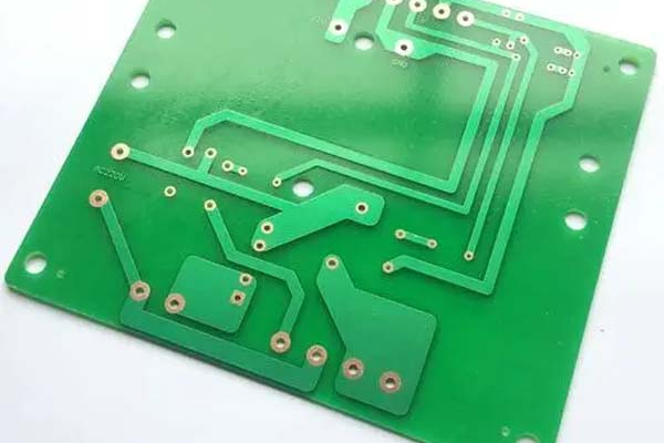
4.1 Dual-Layer Power Supply Design (PMP9458)
The PMP9458 reference design demonstrates effective EMI optimization in a two-layer PCB targeting automotive cluster applications. Key features include:
– Wide input voltage range (6.5V to 38V) suitable for 12V automotive battery systems
– Cascaded buck regulators (LM26003 and LM26420) with automotive AEC-Q100 certification
– Optimized layout with additional input filtering stage for enhanced conducted EMI performance
– Compliance with CISPR 25 Class 5 for conducted emissions
This design proves that effective EMI control is achievable even with cost-effective two-layer boards when proper design techniques are applied.
4.2 USB Charger Solutions (PMP40725 and PMP40960)
Texas Instruments’ PMP40725 (USB Type-A) and PMP40960 (USB Type-C) reference designs showcase optimized EMI performance for automotive USB charger applications. Both designs share common EMI reduction strategies:
– 400kHz switching frequency as a balance between efficiency and EMI
– Front-end filters and PCB layouts specifically optimized for CISPR 25 Class 5 compliance
– Peak efficiency exceeding 95% while maintaining low EMI
– Tested and verified designs that reduce development time
4.3 Isolated Bias Supply (PMP22845)
The PMP22845 reference design demonstrates EMI mitigation techniques for 5kVRMS isolated bias supplies used in applications like traction inverters, battery management systems, and onboard chargers. This design features:
– Highly integrated solution in a 2.65mm tall package
– CISPR 25 Class 5 compliance for radiated emissions
– Low component count and compact footprint
– AEC-Q100 qualification for automotive applications
5.Material Selection and Thermal Management
5.1 PCB Material Considerations
Selecting appropriate PCB materials is crucial for automotive EMI performance:
– High-Tg FR-4 Materials: These materials maintain stability at elevated temperatures common in automotive environments (typically -40°C to +125°C).
– Ceramic-Filled substrates: For high-power applications, these substrates offer better thermal conductivity and stability.
– Low-Loss Laminates: For high-speed signals, specialized laminates help maintain signal integrity while reducing emissions.
5.2 Thermal Management Strategies
Effective thermal management indirectly contributes to EMI control by maintaining component stability:
– Thermal Via Patterns: Strategic placement of thermal vias under power components helps dissipate heat.
– Copper Thickness: Appropriate copper weights ensure adequate current carrying capacity and heat spreading.
– Layer Stackup Optimization: Proper allocation of power and ground planes aids in heat distribution.

6.Design Verification and Compliance Testing
6.1 Simulation-Driven Design
Implementing simulation tools early in the design process helps identify potential EMI issues before prototyping. Signal integrity (SI) and power integrity (PI) simulations can predict resonance points and identify layout improvements, reducing design iterations.
6.2 Pre-Compliance Testing
Conducting pre-compliance testing using methods such as:
– Near-field probing to identify emission hotspots
– Conductance measurements using line impedance stabilization networks (LISNs)
– Comparative testing against known good reference designs
These approaches help identify issues early, reducing the cost and time of full compliance testing.
7.Future Trends in Automotive EMI Management
The automotive industry continues to evolve with several trends impacting EMI design:
– Higher Switching Frequencies: Power converters are moving to higher frequencies to reduce component size, requiring new EMI mitigation approaches.
– 48V Power Systems: The adoption of 48V architectures for mild hybrids presents new EMI challenges.
– Integrated Passives: Embedding passive components within the PCB substrate reduces loop areas and improves EMI performance.
– Wide Bandgap Semiconductors: GaN and SiC devices enable higher efficiency but present new EMI control challenges due to faster switching speeds.
8.Conclusion
Designing PCBs for automotive EMI compliance requires a systematic approach addressing layout, component selection, filtering, and verification. The reference designs and techniques discussed demonstrate that meeting stringent standards like CISPR 25 Class 5 is achievable through careful engineering practices.
As automotive systems continue to increase in complexity, EMI control will remain a critical design consideration. By leveraging proven strategies such as multilayer stackups, proper grounding, advanced switching regulators, and integrated modules, designers can create robust automotive electronics that meet both performance and regulatory requirements.
The key to success lies in addressing EMI considerations early in the design process rather than as an afterthought. With the right approach and attention to detail, automotive PCB designs can achieve the necessary EMI performance while maintaining cost-effectiveness and reliability.
Partner with Us for Your Automotive PCB Projects
Navigating the complexities of automotive EMI compliance requires expertise and precision manufacturing capabilities. Our experience in automotive-grade PCB fabrication and EMI-optimized design can help you create robust solutions that meet stringent industry standards.
Contact us today to discuss how we can support your next automotive project with cutting-edge PCB technology tailored for optimal EMI performance.