1、 Classification of Common LED Bead Models
(1) Divided by power
1. Low power surface mount lamp beads: Models such as 0201, 0402, 0603, 0805, 1206, etc. are all listed here. 0201 LED beads are extremely compact in size, with a length and width of only 0.2mm × 0.1mm. They are commonly used in electronic products that require strict space, such as the backlight of smart watch displays; The size of 0603 LED beads is 0.6mm × 0.3mm, which is a common low-power LED bead widely used in indicator lights on various small circuit boards. Its power is generally around 0.06W, and the operating current is mostly 20mA.
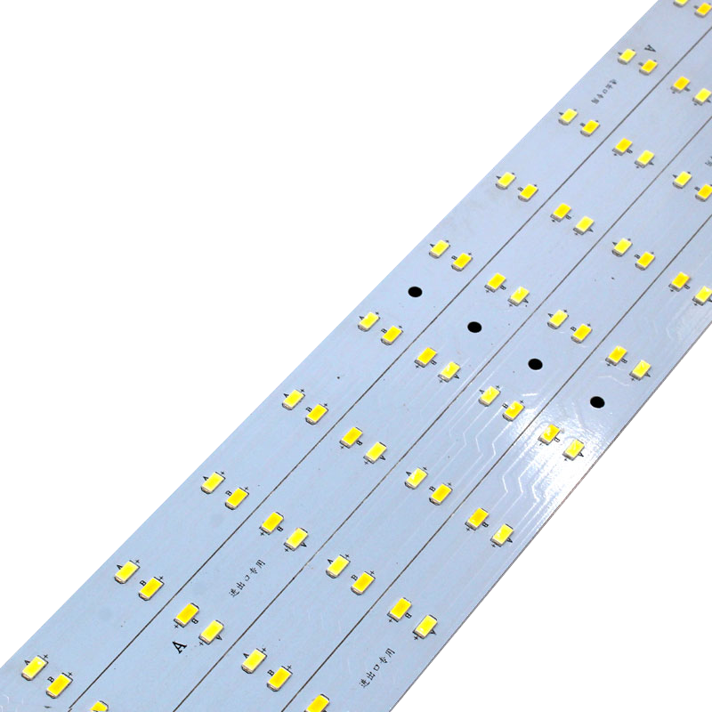
2. Medium power surface mount lamp beads: Typical models include 3014, 3528, 4014, 2835, 5730, 5050, etc. Taking 3528 LED beads as an example, with a specification size of 3.5mm × 2.8mm, it can often be seen on indoor lighting fixtures such as ceiling lights, providing moderate brightness. The power is in the range of 0.1-0.5W, and the operating current is in the range of 30-150mA, with specific values depending on different manufacturers and application scenarios.
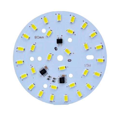
3. High power surface mount lamp beads: 3030, 3535, 7030, etc. belong to this category. The power of 3030 LED beads can reach 1W or even higher, commonly used in outdoor lighting equipment such as street lamps, floodlights, etc. It can provide high brightness lighting effects and meet the needs of long-distance lighting. Its working current is usually above 150mA, and some can even reach 300mA or higher.
(2) Classify by luminous color
1. Monochrome LED beads
1. White light: There are multiple color temperatures for subdivision. Warm white light (NW) has a color temperature between 2700K and 3500K, with soft light and a color tone similar to traditional incandescent lamps. It is suitable for creating a warm and comfortable atmosphere and is commonly used for home bedroom lighting; Positive White Light (PW) has a color temperature between 6000K and 6500K, providing bright and clear light. It is widely used in places such as offices and shopping malls that require high brightness lighting; Cold white light (CW) with a color temperature greater than 6500K and a bluish hue is commonly used in industrial plants, hospitals, and other environments that require high visual clarity. And the color rendering index (CRI) of white LED beads is generally greater than 80, which can better reproduce the true color of objects.
2. Colored light: Red light (R) has a wavelength of 620-630nm and is commonly used as a stop signal for traffic lights, power indicator lights for electronic devices, etc; Green light (G) has a wavelength of 520-530nm and is used for traffic signals and indicating the working status of some instruments and equipment; Blue light (B) has a wavelength of 460-470nm and is not only used for illumination, but also in some special applications such as UV curing and anti-counterfeiting detection.
2. Color changing LED beads (RGB)
1. Three in one RGB: Integrating red, green, and blue chips into one package, by controlling the ratio of the three chips’ luminous intensity, a rich and diverse range of colors can be mixed. Commonly used for creating stage lighting effects, intelligent color changing decorative lighting fixtures, etc., it can achieve colorful lighting changes.
2. Independent RGB: Red, green, and blue chips are independently packaged, which has more advantages in color control accuracy and flexibility compared to three in one RGB. It is commonly used in professional display devices with extremely high color presentation requirements, high-end stage special effects lighting, and other scenes.
3. Special lamp beads
1. High power LED beads: With a power greater than 3W and ultra-high brightness, they are commonly used in large outdoor billboard lighting, sports venue lighting, and other scenarios that require extremely strict brightness requirements. Good heat dissipation design is needed to ensure their stable operation.
2. Plant growth lamp beads: emit specific wavelengths of light to meet the needs of plant photosynthesis. Red light (620-700nm) and blue light (400-520nm) are key wavelengths required for plant growth and are widely used in fields such as plant factories and greenhouse lighting to promote healthy plant growth.
3. Ultraviolet (UV) lamp beads: with a wavelength less than 400nm, can be used for disinfection, cleaning, and curing. It is widely used in medical equipment disinfection, nail polish curing, printing ink curing and other scenarios.
4. Infrared (IR) beads: with a wavelength greater than 700nm, commonly used in night vision monitoring equipment, remote control signal emission, thermal imaging detection, etc., utilizing their invisible light characteristics to achieve specific functions.
2、 Detailed explanation of LED bead usage parameters
(1) Electrical parameters
1. Voltage (V): The voltage required for the normal operation of LED chips varies depending on color and power. Generally speaking, the voltage of red, yellow, orange and other light bulbs is around 1.9-2.3V; The voltage of blue light, green light, white light and other LED chips is in the range of 3.0-3.4V. Before soldering to the PCB circuit board, it is necessary to accurately match the power supply voltage with the rated voltage of the lamp beads. Otherwise, if the voltage is too high, it may burn out the lamp beads, and if the voltage is too low, the lamp beads cannot light up normally.
2. Current (mA): The working current of low-power LED chips is mostly 20mA; the current of medium power LED chips is between 30-150mA; and the current of high-power LED chips usually exceeds 150mA. The magnitude of the current directly affects the brightness of the LED chips. Although excessive current can improve brightness, it can accelerate the aging and even damage of the LED chips; If the current is too low, the brightness will be insufficient. Therefore, in circuit design, precise control of lamp bead current is often achieved through components such as resistors.
3. Power (W): It is obtained by multiplying voltage and current, and is an important indicator for measuring the energy consumption of lamp beads. The power of low-power LED chips is generally 0.06W, medium power is 0.1-0.5W, and high-power LED chips are above 0.5W or even higher. When designing PCB circuit boards, the total power of the lamp beads should be considered to ensure that the power supply can provide sufficient power while avoiding circuit overload.
(2) Optical parameters
1. Luminous flux (lm): represents the total amount of visible light emitted by the lamp bead per unit time. The higher the luminous flux, the brighter the lamp bead. For example, a regular 5730 medium power white LED bead can achieve a luminous flux of 50-60lm, while a high-power LED bead can easily exceed 100lm or even higher. When used for lighting, it is necessary to choose the appropriate luminous flux bead according to actual lighting needs.
2. Light efficiency (lm/W): Reflects the efficiency of the lamp bead in converting electrical energy into light energy, with higher values indicating greater energy savings. High quality LED beads can achieve a luminous efficiency of 100-200lm/W or even higher. In the pursuit of energy conservation and environmental protection, choosing high-efficiency beads can reduce energy consumption and save electricity costs.
3. Light emission angle (°): refers to the range covered by the pearl line of the lamp, and common light emission angles include 120 °, 140 °, etc. For indoor ceiling lights with high requirements for lighting uniformity, it is common to use light beads with a larger emission angle to make the light more evenly illuminate the entire space; Flashlights used for spotlighting use light beads with small emission angles to achieve long-distance strong light irradiation.
4. Color temperature (K): describes the color of light, measured in Kelvin. As mentioned earlier, warm white light at 2700K-3500K, positive white light at 6000K-6500K, cool white light above 6500K, etc. Different color temperatures create different atmospheres. In indoor decoration, display lighting, and other scenes, it is necessary to choose appropriate color temperature light beads according to needs.
5. Color rendering index (CRI): measures the degree of restoration of the true color of an object under illumination. The closer the value is to 100, the better the color rendering. In places with high requirements for color recognition, such as clothing display areas in shopping malls, museum exhibition halls, etc., LED light beads with a CRI greater than 80 or even higher should be selected to ensure that the colors of goods or exhibits are truly presented.
(3) Other parameters
1. Service life (hours): refers to the expected duration of illumination of LED beads under normal working conditions. The service life of high-quality LED chips can generally reach 20000-50000 hours or even longer. In long-term use of lighting equipment, choosing long-lasting lamp beads can reduce maintenance costs and improve equipment stability.
2. Packaging: It determines the physical shape and size of the lamp bead, which has a significant impact on welding and application. Common packaging options include direct insertion and surface mount (SMD). Direct insertion lamp beads have pins that are easy to manually solder and are commonly used in circuits that do not require high spatial layout; Surface mount LED chips have no pins and can be directly mounted on PCB circuit boards, making them suitable for high-density circuit design and reducing the size of the circuit board.
In the process of soldering LED light beads on PCB circuit boards, only by comprehensively mastering the characteristics and usage parameters of various LED light bead models can the most suitable product be selected from numerous light beads according to specific application scenarios, ensuring smooth soldering and enabling LED light beads to perform at their best in the final product.