Table of Contents
What is an LDO (Low Dropout Regulator)?
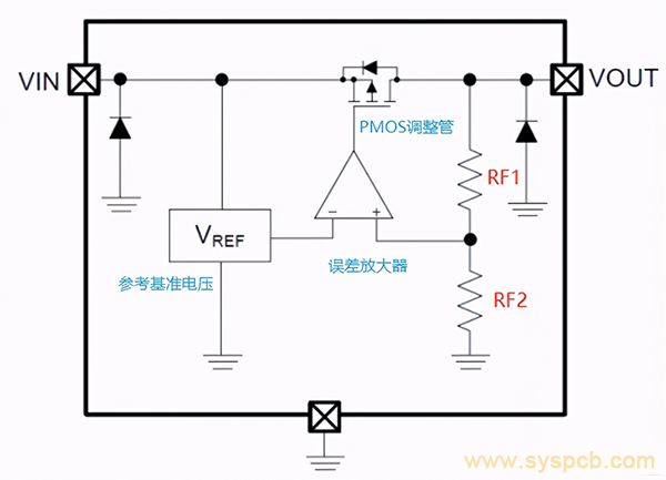
An LDO is a type of linear voltage regulator that provides a stable output voltage with a small difference (dropout voltage) between the input and output. Unlike traditional voltage regulators, which require a higher input voltage to maintain a constant output, LDOs are designed to operate with a minimal difference between input and output, making them particularly useful for applications with low input voltages or those requiring high efficiency.
For example, an LDO may provide a regulated 5V output from a 5.5V input, with a dropout voltage of just 0.5V. This efficiency in voltage regulation makes LDOs ideal for portable devices, where power consumption and heat dissipation are critical factors.
Understanding LDO Output Voltage
The output voltage of an LDO is the voltage that is delivered to the load (the powered circuit or device). It is regulated and held constant by the LDO, regardless of variations in the input voltage (as long as the input voltage is above the LDO’s minimum requirement) and changes in the load current.
Key factors that influence the output voltage of an LDO include:
1. Dropout Voltage (V_droop)
The dropout voltage is the minimum difference between the input voltage and the output voltage required for the LDO to maintain regulation. It is a critical parameter for ensuring that the output voltage stays within acceptable limits.
Typical Range: Dropout voltage is typically low for LDOs, ranging from a few millivolts for ultra-low dropout (ULDO) designs to a few volts for high-power designs. LDOs with a low dropout voltage are preferred for battery-powered applications because they allow more efficient use of the battery voltage.
Factors Affecting Dropout Voltage: The dropout voltage is primarily determined by the pass transistor type (BJT, MOSFET, etc.), the LDO’s design, and the output current. Generally, MOSFET-based LDOs tend to have lower dropout voltages compared to BJT-based designs.
2. Load Regulation
Load regulation refers to how well the output voltage of an LDO stays constant when the load current changes. Ideally, an LDO should maintain a constant output voltage regardless of the load. However, in reality, a small voltage drop may occur as the load current increases.
Impact on Output Voltage: A poor load regulation could result in fluctuations in the output voltage when the load changes, which can lead to instability in the powered circuit, especially for sensitive analog or digital components.
Design Considerations: The LDO design should account for optimal load regulation by using appropriate feedback mechanisms and compensation to minimize output voltage variations.
3. Line Regulation
Line regulation is the ability of the LDO to maintain a constant output voltage despite variations in the input voltage. An LDO with poor line regulation will experience significant changes in its output voltage as the input voltage fluctuates, which can cause issues in the overall performance of the system.
Impact on Output Voltage: Good line regulation ensures that the LDO can maintain a stable output even when the input voltage rises or falls due to variations in the power supply or battery voltage.
Design Considerations: Line regulation can be improved by optimizing the error amplifier and using high-quality reference voltages.
4. Thermal Performance and Power Dissipation
The output voltage stability is also influenced by thermal performance and power dissipation. LDOs inherently dissipate power as heat, and if the regulator is not adequately cooled, this could affect its ability to regulate the output voltage properly.
Thermal Shutdown: In cases of excessive heat buildup, LDOs often include thermal shutdown protection to prevent damage to the regulator. However, excessive power dissipation could still lead to temporary output voltage instability before the thermal protection kicks in.
Thermal Management: To mitigate this, it’s important to choose an LDO with appropriate thermal performance and design the circuit for efficient heat dissipation.
5. Noise and Ripple Performance
The LDO output voltage is susceptible to noise and ripple, especially in precision analog and RF circuits. Noise and ripple are fluctuations in the output voltage caused by internal components of the LDO, such as the pass transistor and the feedback loop.
Low Noise LDOs: In sensitive applications, low-noise LDOs are required to minimize the impact of these fluctuations. These LDOs are designed with special filtering techniques and ultra-low noise reference voltages to reduce ripple and maintain a clean output.
Filter Capacitors: Proper capacitor selection at the output and input can also help reduce noise and ripple in the output voltage.
Factors to Consider When Designing LDO Output Voltage Circuits
When designing a power supply circuit that incorporates an LDO, it’s important to consider the following factors to ensure stable and reliable output voltage:
1. Input Voltage Range
Ensure the input voltage is always above the dropout voltage of the LDO to maintain a stable output. For battery-powered devices, choose LDOs with a very low dropout voltage to maximize the battery life.
2. Output Voltage Accuracy
Most LDOs offer a fixed output voltage, but for applications requiring a custom voltage, adjustable LDOs are available. The output voltage can be fine-tuned with external resistors, but care must be taken to ensure accuracy within the required tolerance.
3. Capacitor Selection
Proper capacitors must be selected for the input and output sides of the LDO to minimize voltage spikes, reduce noise, and ensure stability. High-quality ceramic capacitors with low ESR (Equivalent Series Resistance) are typically recommended.
4. Thermal Management
When designing for high-power applications, ensure the LDO is capable of dissipating the heat generated from power loss. Use heat sinks, proper PCB layout techniques, and consider the use of thermal pads or vias to enhance heat dissipation.
Conclusion
The output voltage of an LDO is one of the most critical parameters for ensuring stable operation in electronic circuits. By understanding the factors that affect LDO output voltage—such as dropout voltage, load regulation, line regulation, thermal performance, and noise—designers can optimize their power supply circuits to meet the specific needs of their applications. Careful component selection and design techniques are essential for achieving reliable and efficient LDO performance, especially in sensitive or power-constrained systems.
Hot tags: output voltage pcb board, voltage range pcb board, pcb board, power chip, power fluctuations pcb board, undervoltage pcb board, reference voltage, temperature drift, stable voltage pcb board, pcb boards, Customized, cheap, quotation, suppliers, factory, manufacturer, manufacturing, manufacturing services