Abstract: Diodes are very commonly used basic components. This article China PCB factory SysPCB mainly introduces its application in circuit design. The following summarizes some of the functions of diodes, such as anti-reverse, rectification, voltage regulation, freewheeling, detection, voltage multiplier, clamping, and envelope detection.
1. Anti- reverse
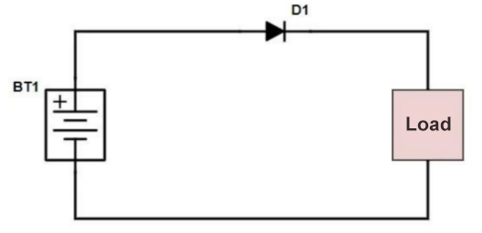
In the main circuit, a diode is connected in series to realize the simplest and most reliable low-cost anti-reverse connection function circuit by utilizing the unidirectional conduction characteristics of the diode. This low-cost solution is generally used in small current applications, such as small toys.
Because the diode is turned on, there will be a conduction voltage drop of 0.7V (silicon tube). If the actual current is large, a heat loss will be generated, which will cause heat generation. And if the reverse connection voltage is very large, it will also break down the diode itself if it exceeds the reverse cut-off voltage, resulting in the failure of the diode, then the function of preventing reverse connection cannot be achieved, so it cannot protect the subsequent circuit.
2. Rectification
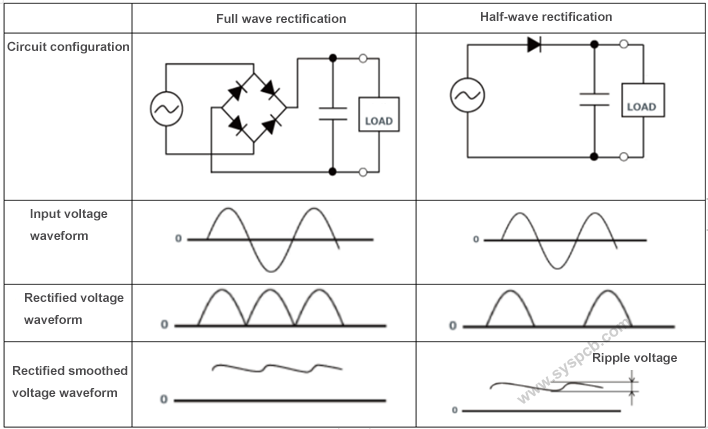
The function of the rectifier circuit is to convert the alternating current with a lower voltage output by the AC step-down circuit into a unidirectional pulsating direct current. This is the rectification process of the alternating current. The rectifier circuit is mainly composed of rectifier diodes. The voltage after the rectifier circuit is no longer an AC voltage, but a mixed voltage containing a DC voltage and an AC voltage, which is customarily called a unidirectional pulsating DC voltage.
3. Voltage stabilization
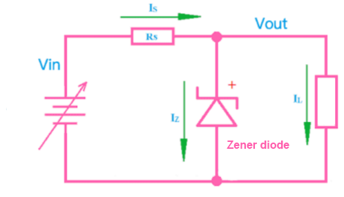
The diode with voltage stabilization is called Zener diode, the English name is Zener diode, also known as Zener diode. Using the reverse breakdown state of the PN junction, the current can be changed in a wide range while the voltage is basically unchanged. The basic circuit structure is shown in the figure below.
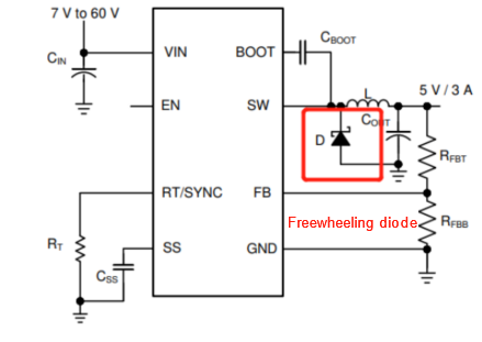
4. Freewheeling effect
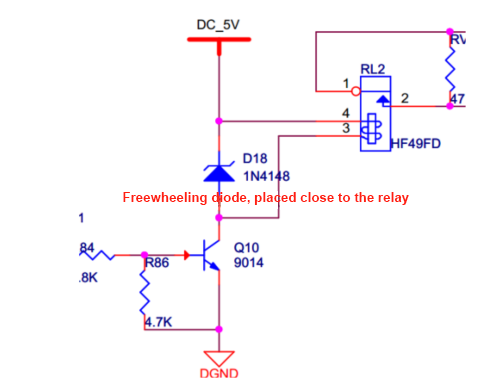
Freewheeling diodes are connected in parallel at both ends of the coil (inductive components), and when the coil passes current, an induced electromotive force will be generated at both ends. When the current disappears, its induced electromotive force produces a reverse voltage on the components in the circuit. When the reverse voltage is higher than the reverse breakdown voltage of the components, it will cause damage to the components such as triode. The freewheeling diode is connected in parallel at both ends of the line. When the current flowing through the coil disappears, the induced electromotive force generated by the coil is consumed by the circuit formed by the diode and the coil. Clump and protect the safety of other components in the circuit. The common circuit structure is as follows.
Or the freewheeling diode in the BUCK chip circuit.
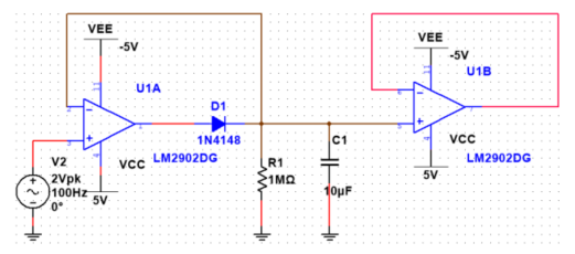
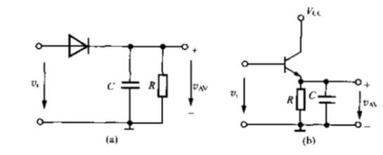
5. Peak Detection effect
The peak detection circuit detects the maximum value of the input signal amplitude. Its working principle is: when the input voltage amplitude is greater than the forward voltage of the diode, the diode is turned on, the output voltage is applied to the capacitor C1, and the two ends of the capacitor are charged. When the input voltage amplitude is lower than the previous input voltage amplitude, the diode is in a reverse-biased cut-off state. At this time, the voltage across the capacitor remains basically unchanged; if a signal is input again, the input voltage amplitude must be higher than the voltage across the capacitor at this time (that is, the forward voltage applied to the diode), and the diode can be turned on.
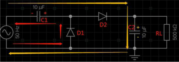
6. Double voltage
The following figure is a schematic diagram of a double voltage circuit, and its working process is roughly analyzed as follows:
During the negative half cycle of the power supply, the diode D1 is turned on, D2 is turned off, the current flows from the lower end of the power supply through D1, and C1 returns to the power supply, so the capacitor C1 is positive on the right and negative on the left, as shown by the red arrow in the figure below.
During the positive half cycle of the power supply, the voltage on the capacitor C1 superimposes the power supply voltage, so that the diode D2 is turned on, the diode D1 is turned off, the capacitor C2 is positive and the bottom is negative, and the peak voltage can reach twice the peak voltage of the power supply, that is, double the voltage.
The current trend during this half cycle is shown by the orange arrow in the figure below:
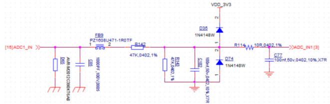
7. ADC detection port voltage clamping function
In some ADC detection circuits, two diodes are used for clamping protection. The principle is very simple. 0.7V is the turn-on voltage drop of D1 and D2. When the incoming voltage from Vin is greater than or equal to 3.3V+0.7V, D35 is turned on and Vout It will be clamped at 4V; when Vin is less than or equal to -0.7V, Vout is clamped at about -0.7V.
8. Envelope detection function
The circuit structure is shown below. The design point is that the time constant of the RC needs to be much larger than the period of the carrier frequency and much smaller than the period of the modulation signal.
Hot tags: Diodes application, pcb design, conponent Diodes, diodes, pc board design, pcb board design, circuit board design, circuit design, electronic circuit simulator, Customized, cheap, quotation, suppliers, factory, manufacturer, manufacturing, manufacturing services