In today’s rapidly developing electronic manufacturing industry, surface mount technology (SMT) has become the core link of PCB assembly. As the “brain” of the SMT production line, the programming level of the SMT machine directly determines production efficiency, mounting accuracy, and final product quality. For SMT companies pursuing excellence, a deep understanding and mastery of machine programming is the key to achieving automated and intelligent production and enhancing core competitiveness. This article will systematically analyze the core process, key points, and optimization strategies of SMT machine programming, helping enterprises unleash equipment potential and move towards efficient lean production.
Table of Contents
1、 Programming Fundamentals: Environment Building and Basic Cognition
Sharp tools make good work. Successful SMT programming begins with a solid foundation and a suitable environment.
1. Gain a deep understanding of devices and software:
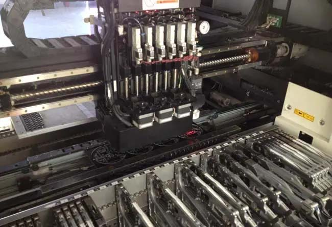
Hardware features: Programmers must be familiar with the specific model and hardware structure of the surface mount machine used (such as nozzle type, flight head configuration, camera system accuracy, conveyor belt mechanism, PCB positioning method). The performance parameters of different devices (speed, accuracy, feeder capacity) directly affect programming strategies.
Software mastery: Proficiency in specialized programming software for SMT machines is a core skill. This includes familiarity with software interface layout, project creation and management, component library operations, visual calibration tools, coordinate system settings, and rich debugging features such as single step execution, breakpoint settings, and variable monitoring. Understanding the latest version features of software is also crucial.
2. Build a robust programming environment:
Software installation and authorization: Strictly install programming software according to supplier requirements, complete necessary authorization activation to obtain full functionality.
Hardware connection and configuration: Ensure stable communication between the computer and the SMT machine (serial port/Ethernet), and correctly configure peripheral devices such as sensors and actuators.
Efficient toolchain: Choose a suitable code editor (such as VS Code, IntelliJ IDEA) and install relevant plugins (syntax highlighting, SMT support), master the use of debuggers (GDB, LLDB) and performance analysis tools (gprof, Valgrind).
2、 Core programming process: from data to instructions
SMT programming is a system engineering that converts design intent into precise machine actions, mainly consisting of the following key steps:
1. Data preparation and import:

BOM organization: Obtain and organize the electronic BOM provided by the customer (usually in Excel format) to ensure the accuracy of component part numbers, specifications, and models.
Coordinate acquisition: This is the foundation of accuracy. The ideal situation is for the customer to provide accurate coordinate files (such as Gerber exported coordinates). If not available, a scanner needs to be used to generate CAD coordinates for PCB sampling, and then combined with BOM. Programming software needs to be able to correctly parse imported Gerber or coordinate files.
PCB information input: Accurately input information such as PCB size, thickness, Mark point (reference point) position, and type.
2. Coordinate system setting and calibration:
Understanding coordinate systems: Clearly distinguish between the world coordinate system (machine reference), machine coordinate system (equipment itself), and component coordinate system (component center).
Origin setting: Precisely define the origin position of the PCB on the machine platform (usually aligned with the PCB design origin or major Mark points).
Coordinate transformation: Master coordinate calculation and transformation methods to ensure that the design coordinates can be accurately mapped to the machine coordinate space.
3. Creation and management of component libraries:
Detailed component database: This is the core point of programming. Accurate physical parameters must be entered for each component, including length, width, height, pin spacing/quantity, shape characteristics, weight, appropriate nozzle model, and feeder type (Tape, Tray, Stick). A detailed description (such as identification of special-shaped, precision, and sensitive components) is crucial for subsequent optimization and error prevention.
Pick and place parameters: Set optimized pick vacuum, height, speed, as well as placement pressure, height, delayed release parameters for different component characteristics (such as fragile LED, micro BGA) to prevent component damage or flying parts.
Maintenance and updates: Establishing a standard component library and continuously maintaining and updating it is the key to improving programming efficiency and accuracy.
4. Programming and optimization:
Basic mounting sequence: Based on coordinate data and component library, generate the initial sequence of material retrieval, identification, and mounting instructions.
Path optimization: the source of core efficiency. Using software optimization algorithms, calculate the shortest travel path optimization for the movement of the mounting head to minimize idle travel time. Consider the position of the feeder, the order of component picking, and the distribution of mounting points.
Flight head allocation: For multi mounted head devices, allocate tasks to each head reasonably, balance loads, avoid waiting or collision between heads, and achieve parallel and efficient operations.
Special component strategy: Develop specialized picking, identification (which may require special light sources or angles), and mounting strategies for special-shaped components (such as large inductors and connectors), high-precision components (fine pitch QFP, uBGA), and sensitive components (ESD sensitive devices).
Multi layer board technique: For multi-layer boards, choose the appropriate alignment method (edge alignment, Mark point alignment), set stacking parameters reasonably, and handle special structures such as jumpers.
3、 Debugging, Validation, and Continuous Optimization: Ensuring Program Reliability
Programming completion is not the end, rigorous debugging and verification are the guarantee of high-quality production.
1. Simulated operation:
Fully utilize the 3D simulation function of the software to observe the entire mounting process in a virtual environment, and check for any issues with component position, angle, path logic, head interference, feeder switching, etc. This is a safe and efficient means of discovering potential errors and optimizing programs.
2. Online debugging and first article confirmation:
Teaching calibration: Perform teaching calibration of key components on the machine (material sampling teaching, patch teaching), and fine tune coordinates and angles.
Empty operation: Run the program without placing any components, observe whether the equipment operates smoothly, whether the axis movements, feeder switching, and nozzle movements are normal.
First piece mounting and inspection: Conduct first piece (or small batch) actual mounting, carefully inspect the mounting position, polarity, offset, monument, bridge connection and other defects of each component using AOI (automatic optical inspection) or manual microscope. Fine tune program parameters (compensation value, mounting height, speed, etc.) based on the results.
3. Troubleshooting and Prevention:
Common faults: Familiar with programming. Possible types of faults include program logic errors, improper parameter settings, coordinate/angle deviations, component recognition failures, feeder/nozzle configuration errors, communication interruptions, etc.

Debugging skills: Proficient in using tools such as single step execution, breakpoint debugging, variable monitoring, and log output to quickly locate the root cause of problems.
Establish standards: Develop standardized programming, debugging, and verification processes and documentation to reduce human errors.
4. Performance monitoring and continuous optimization:
Data analysis: Collect production data (installation cycle time, material rejection rate, equipment utilization rate) and analyze bottlenecks.
Iterative optimization: Based on the analysis results, continuously optimize the program: further shorten the path, adjust the layout of the feeder (reduce the flying distance), optimize the nozzle replacement strategy, balance the workload of each mounting head, optimize recognition parameters to reduce misjudgments.
Knowledge accumulation: Consolidate optimization experience and best practices into standard component libraries and programming templates.
4、 Future prospects: Intelligence and integration
SMT programming technology is developing towards a more intelligent, efficient, and integrated direction:
Intelligent programming: Combining AI technology to achieve automatic component recognition, automatic library generation, intelligent board assembly, more powerful adaptive path optimization, and predictive maintenance based on PCB design files.
Higher precision and efficiency: With the application of precision cameras, high-speed motion control, and advanced algorithms, the mounting accuracy (such as 01005, 0.3mm pitch BGA) and speed (CPH) will continue to improve.
Multi functional integration: The programming platform will further integrate SPI (solder paste inspection) AOI、 Even dispensing, repairing and other functional instructions can achieve integrated process control and data closed-loop.
Digital twins and cloud platforms: utilizing digital twin technology for more realistic virtual debugging; The cloud platform enables centralized program management, version control, remote debugging, and knowledge sharing.
Conclusion
SMT machine programming is far from simple coordinate input. It is a systems engineering that integrates knowledge of mechanics, electronics, computer science, and materials science, and highly relies on practical experience. From precise data preparation and rigorous component library management to efficient path planning and meticulous debugging and verification, every step is related to production efficiency and quality. Only by continuously investing resources, cultivating professional programming talents, establishing standardized processes, embracing intelligent tools, and continuously optimizing programming practices can enterprises harness the surging power of SMT equipment in fierce market competition, achieve high-quality, high-efficiency, and highly flexible intelligent manufacturing, and win future opportunities.