Table of Contents
Introduction to Electronic Components
Electronic components form the fundamental building blocks of all modern electronic devices, from smartphones to industrial control systems. These components are broadly categorized into two distinct types: active components and passive components. Understanding the differences between these components, their characteristics, and their applications is essential for effective PCB design and manufacturing.
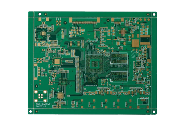
At SysPCB, we specialize in manufacturing advanced PCBs that optimally integrate both active and passive components to create reliable, high-performance electronic systems. This guide explores the key differences, applications, and PCB design considerations for these critical electronic elements.
Ⅰ.What are Passive Components?
Passive components are electronic elements that cannot introduce net energy into a circuit nor can they amplify signals. They either consume energy or store it in an electric or magnetic field. These components do not require any external power source for their operation and typically have a linear response.
Key Characteristics of Passive Components:
•No power gain: They cannot amplify signals
•Linear behavior (mostly): Follow Ohm’s Law directly
•No directionality (mostly): Many work equally well in both directions
•Two-terminal devices: Simple connection requirements
Common Types of Passive Components:
1. Resistors
•Function: Oppose current flow, divide voltages, limit current
•PCB Considerations: Power rating, temperature coefficient, placement for heat dissipation
•Types: Fixed, variable, surface mount, through-hole
•Applications: Voltage dividers, current limiting, pull-up/pull-down networks
2. Capacitors
•Function: Store electrical energy, filter signals, block DC while passing AC
•PCB Considerations: ESR (Equivalent Series Resistance), voltage rating, temperature stability
•Types: Ceramic, electrolytic, tantalum, film
•Applications: Power supply filtering, coupling/decoupling, timing circuits
3. Inductors
•Function: Store energy in magnetic fields, oppose changes in current
•PCB Considerations: Electromagnetic interference, placement away from sensitive components
•Types: Air core, ferrite core, toroidal
•Applications: RF circuits, power supplies, filtering
4. Transformers
•Function: Transfer electrical energy between circuits through electromagnetic induction
•PCB Considerations: Size, weight, electromagnetic shielding
•Types: Power, audio, RF
•Applications: Voltage conversion, isolation, impedance matching
5. Diodes (Considered passive in most contexts)
•Function: Allow current flow in one direction only
•PCB Considerations: Heat dissipation, current rating, reverse recovery time
•Types: Rectifier, Zener, LED, Schottky
•Applications: Rectification, voltage regulation, protection
Table: Passive Components Comparison
| Component | Primary Function | Key Parameters | PCB Design Considerations |
| Resistor | Current limitation | Resistance, power rating, tolerance | Thermal management, signal integrity |
| Capacitor | Energy storage | Capacitance, voltage rating, ESR | Decoupling placement, high-frequency response |
| Inductor | Energy storage (magnetic) | Inductance, current rating, Q factor | EMI control, placement isolation |
| Transformer | Voltage conversion | Turns ratio, power rating, frequency | Size accommodation, electromagnetic isolation |
| Diode | Rectification | Forward voltage, reverse recovery | Heat dissipation, current capacity |
Ⅱ.What are Active Components?
Active components are electronic elements that can amplify signals and introduce energy into a circuit. They typically require an external power source for operation and can control electron flow through various mechanisms, often exhibiting non-linear behavior.
Key Characteristics of Active Components:
•Provide power gain: Can amplify signals
•Non-linear behavior: Do not strictly follow Ohm’s Law
•Directional: Have specific input and output terminals
•Typically three or more terminals: More complex connection requirements
Common Types of Active Components:
1. Transistors
•Function: Signal amplification, switching, regulation
•PCB Considerations: Heat dissipation, mounting, ESD protection
•Types: BJT, MOSFET, JFET, IGBT
•Applications: Amplifiers, switches, power regulation
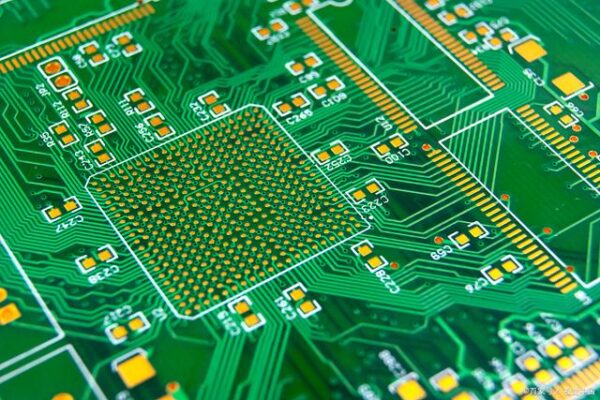
2. Integrated Circuits (ICs)
•Function: Complete electronic circuits in miniature form
•PCB Considerations: Pin spacing, thermal management, decoupling
•Types: Analog, digital, mixed-signal, microcontrollers
•Applications: Processing, control, interface, memory

3. Operational Amplifiers (Op-Amps)
•Function: Differential amplification, signal conditioning
•PCB Considerations: Feedback network layout, power supply bypassing
•Types: General purpose, precision, high-speed
•Applications: Filters, comparators, instrumentation
4. Voltage Regulators
•Function: Provide stable voltage output from variable input
•PCB Considerations: Heat sinking, input/output filtering
•Types: Linear, switching
•Applications: Power supply regulation, voltage reference
5. Microprocessors/Microcontrollers
•Function: Digital data processing and control
•PCB Considerations: Signal integrity, power distribution, clock management
•Types: 8-bit, 16-bit, 32-bit, application-specific
•Applications: Embedded systems, control systems, computing
Table: Active Components Comparison
| Component | Primary Function | Key Parameters | PCB Design Considerations |
| Transistor | Switching/Amplification | Gain, frequency, power | Thermal management, ESD protection |
| IC | Multiple functions | Package type, pin count, speed | Decoupling, signal integrity, thermal relief |
| Op-Amp | Signal amplification | Bandwidth, slew rate, offset | Ground plane integrity, feedback layout |
| Voltage Regulator | Voltage stabilization | Dropout voltage, current | Heat dissipation, input/output filtering |
| Microcontroller | Digital processing | Architecture, speed, I/O | Power distribution, clock routing, EMI control |
Ⅲ.Key Differences Between Active and Passive Components
| Characteristic | Active Components | Passive Components |
| Power Gain | Can provide power gain | Cannot provide power gain |
| Energy Source | Require external power source | Do not require external power |
| Function | Amplify, oscillate, generate | Resist, store, filter, dissipate |
| Linearity | Typically non-linear | Typically linear |
| Directionality | Have specific direction | Usually non-directional |
| Complexity | More complex | Simpler |
| Cost | Generally more expensive | Generally less expensive |
| Failure Rate | Higher failure rate | Lower failure rate |
Ⅳ.PCB Design Considerations for Active and Passive Components
1. Component Placement Strategies
•Signal Flow: Arrange components according to signal path
•Thermal Management: Position heat-generating components optimally
•Decoupling: Place decoupling capacitors close to IC power pins
•Grouping: Cluster related components together
2. Thermal Management
•Heat Dissipation: Provide adequate copper area for heat sinking
•Thermal Vias: Use thermal vias under hot components
•Component Spacing: Allow adequate air flow around components
•Thermal Relief: Use thermal relief patterns for soldering
3. Signal Integrity Considerations
•Trace Routing: Maintain proper trace width and spacing
•Impedance Matching: Match impedances for high-frequency signals
•Ground Planes: Use continuous ground planes for return paths
•Shielding: Implement shielding for sensitive circuits
4. Power Distribution
•Power Planes: Use dedicated power planes when possible
•Decoupling Strategy: Implement hierarchical decoupling
•Current Capacity: Ensure traces can handle required current
•Voltage Drop: Minimize voltage drop in power distribution
5. Manufacturing Considerations
•Component Size: Balance performance with manufacturability
•Assembly Process: Design for automated assembly
•Test Access: Provide test points for critical signals
•Rework Ability: Allow for component replacement if needed
Ⅴ.Advanced Integration Techniques
1. Embedded Components
•Passive Integration: Embed resistors and capacitors within PCB layers
•Active Integration: Emerging technologies for embedding active components
•Benefits: Space savings, improved performance, reduced parasitics
2. 3D Packaging
•Component Stacking: Stack components to save board space
•Package-on-Package: Stack IC packages vertically
•System-in-Package: Integrate multiple components in single package
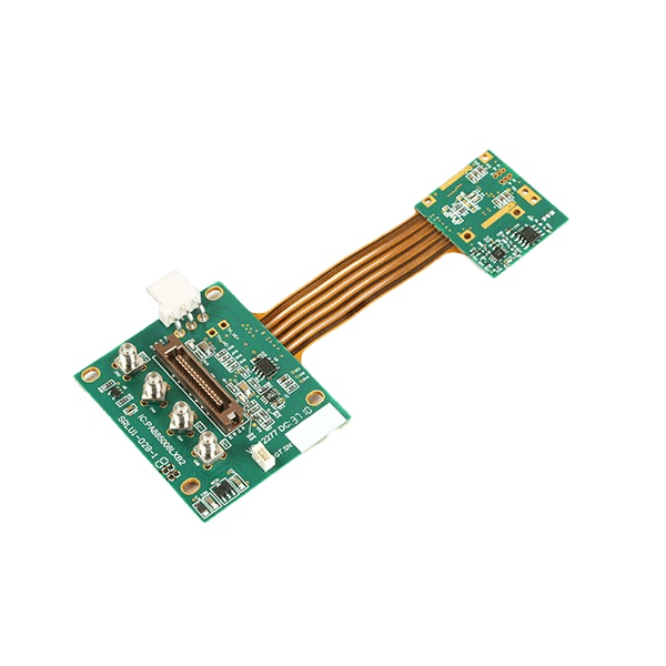
3. High-Density Interconnect (HDI)
•Microvias: Use microvias for dense component placement
•Fine Pitch: Accommodate fine-pitch components
•Any-Layer HDI: Maximum routing flexibility for complex designs
Ⅵ.Future Trends in Component Technology
1. Miniaturization Continuation
•Smaller Packages: Continued reduction in component sizes
•Higher Integration: More functions in smaller packages
•Advanced Materials: New materials enabling smaller components
2. Smart Passive Components
•Integrated Sensing: Passive components with built-in monitoring
•Self-Protection: Components with built-in protection features
•Programmable Passives: Adjustable passive components
3. Wide Bandgap Semiconductors
•GaN and SiC: New active component technologies
•Higher Efficiency: Improved power handling capabilities
•Higher Frequency: Operation at higher frequencies
4. Sustainable Components
•RoHS Compliance: Lead-free and environmentally friendly components
•Recyclability: Components designed for easier recycling
•Energy Efficiency: Components with lower power consumption
Conclusion
Understanding the distinction between active and passive components is fundamental to effective electronic circuit design and PCB layout. While passive components provide the essential foundation of resistance, capacitance, and inductance, active components bring the capability for amplification, switching, and complex processing functions.
Successful PCB design requires careful consideration of both component types, their interactions, and their specific requirements for optimal performance. At SysPCB, we leverage our expertise in PCB manufacturing to help designers effectively integrate both active and passive components, ensuring reliable, high-performance electronic systems.
By staying current with the latest component technologies and manufacturing techniques, we enable our customers to create innovative products that meet the demanding requirements of today’s electronic markets.
Need expert guidance on component selection and PCB layout?
→ [Contact our technical team for a design consultation]
→ [Download our component placement guidelines]
→ [Request our manufacturing design rule checklist]